Formula Sound GUARDIAN CX10 Руководство пользователя - Страница 2
Просмотреть онлайн или скачать pdf Руководство пользователя для Оборудование для звукозаписи Formula Sound GUARDIAN CX10. Formula Sound GUARDIAN CX10 5 страниц. Priority/evacuation interface
General information
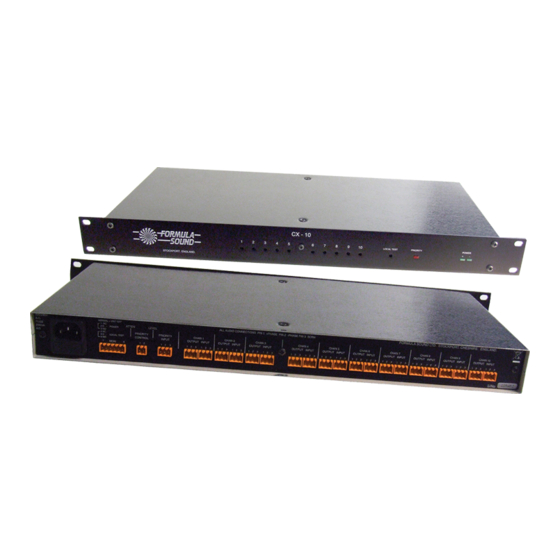
The CX10 provides a priority input into an audio system of up to 10 channels in a 19" 1RU package. The CX10 may
be used with any sound system where a priority override facility is required e.g. Entertainment venue, shopping
centres, malls, cruise ships or any public area where fire, security or other important announcements are required.
The CX10 features unity gain, balanced line level inputs, and outputs. The signal chains use low noise, low
distortion pro audio circuits so as to be almost transparent in use. A balanced line level priority input is incorporated
(microphone level priority input is available to order). The trigger input is via a closing contact which must be fully
isolated.
Operation
The CX10 has been designed to be connected between the mixer/zoner (or pre amp) of an audio system and the
power amplifiers. The priority signal (e.g. evacuation message) is a line level input and is connected to the priority
input socket and the control input is connected to the fire alarm or whatever triggering method is required.
In normal mode programme signals pass through the 10 audio channels of the CX10 with no change in level.
When the unit is triggered the incoming programme level is attenuated and the priority signal is mixed into the ten
outputs. When the unit is reset the priority signal is removed and the programme will fade back to the original
volume.
The attenuation level is fully adjustable, as is the priority signal level (The priority signal level is individually
adjustable to the various outputs). A local test button is provided for setting up the system.
Remote monitoring of units is possible by using the switch contacts available from the local test button, and the
unit-powered relay (6 way connector). (Both provide single pole change over-contacts).
If more than 10 channels are required multiple units may be fitted. The trigger input may be paralleled to several
units so long as the polarity is maintained. E.g. pin 1 to pin 1 - pin 2 to pin 2.
In a normal situation the connections to the CX10 can be considered as a straight-through link which will not affect
the normal operation of the system. Only when the CX10 is triggered will there be any effect on the system.
Set up
On the back panel connect the line level priority source to the priority input and connect the trigger (normally a fire
alarm) to the priority control connector (must be isolated contacts that close to trigger).
Connect the mixer/zoner outputs to the connectors marked "INPUT". The adjacent connector to each input is the
output for that channel (marked "OUT"). Connect the output to whatever was previously connected to the
mixer/zoner (usually this will be equalisation, crossover or amplifiers).
To test the unit use a small screwdriver to press the "LOCAL TEST" switch that is recessed behind the front panel,
the "PRIORITY" LED on the front panel should illuminate. Press the "LOCAL TEST" switch again and after a few
seconds the "PRIORITY" LED will go out (the "LOCAL TEST" switch also has an LED which is illuminated and
visable through the recessed hole when the "LOCAL TEST" switch is on).
A set of isolated contacts on the "LOCAL TEST" switch are available at the monitor ("MON") connector pins 4,5&6
allowing a remote monitoring circuit to be connected (eg "NO" contacts can be used to close a circuit that lights a
LED). There is also a set of isolated contacts at the monitor ("MON") connector pins 1,2&3 allowing a remote
monitoring circuit to be connected that will monitor the power status of the unit (eg "NO" contacts can be used to
close a circuit that lights a LED or "NC" contacts can be used in which case the LED will go out).
Through the front panel using a small flat blade screwdriver adjust the potentiometers marked 1 – 10 fully clockwise.
Page 1