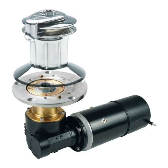
Andersen RA2050001400 Руководство по эксплуатации - Страница 7
Просмотреть онлайн или скачать pdf Руководство по эксплуатации для Лебедки Andersen RA2050001400. Andersen RA2050001400 18 страниц. To suit self-tailing winch sizes 46,50

INSTALLATION INSTRUCTIONS
STEP 3
*Note: It is extremely important that the motor is aligned correctly with the winch.
Non-aligned motors will be noisy and gear wear will be accelerated.
*Note: It is important that two or more people are involved with Step 3.
• Remove clamping ring [6] from drive shaft housing [21] of motor unit.
• Fit the supplied M6 eye bolt [A6] to the top of the motor drive shaft [12] and attach a strong
rope to facilitate lifting the motor unit up into position through the hole in the deck, winch base
and clamping ring as shown below.
• Using the rope, raise the motor unit so that the drive shaft protrudes through the large hole in
the deck and winch base. A lifting device is recommended when raising the motor unit.
• Rotate the motor unit into the required position to suit the under deck cavity, ensuring that the
motor is aligned properly – The protruding octagonal detail on the drive shaft housing [16] flange
must fit snugly into the octagonal recess in the winch base to allow the motor top flange to fit
flush with the underside of the winch base (refer to diagrams below).
*Note: Ensure that the O-ring [9] on top of the drive shaft housing [21] is in place in its groove.
• Insure that the locking grub screw [5] in the clamping ring [6] is not protruding beyond the
upper surface of the clamping ring, when fitting the clamping ring.
• Fit and securely tighten the clamping ring [6] using the pin spanner [A8] provided.
• Tighten the locking grub screw [5] when the clamping ring [6] is securely in place.
*Note: Do not use a sealant between the flange and winch base. An O-ring insures a waterproof
connection. Extra waterproofing can be achieved by applying sealant to the top of the winch base
around the clamping ring after installation (make sure no sealant comes onto the sealing ring [7] ).
Incorrect mating of drive
shaft housing top flange with
underside of winch base
Grub Screw
5
Clamping Ring
6
Deck Plate or
Winch Base
Motor flange
Non-aligned hole in
deck preventing correct
motor alignment
E1 Single Speed Electric Motor Unit, 12V & 24V
To Suit Self-Tailing Winch Sizes 46,50
Correct mating of drive shaft
housing top flange with
underside of winch base
Grub Screw
5
Clamping Ring
6
Clamping ring
Deck Plate or
not parrallel to
Winch Base
deck plate
Grub screw
protruding too far
Inadequate underdeck
clearance preventing
correct motor alignment
Motor unit
lifting eye bolt
90°
p7
