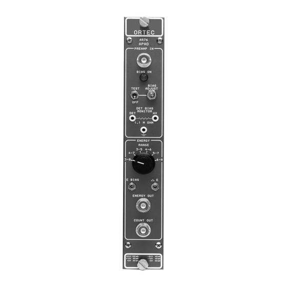
Advanced Measurement Technology ORTEC A-576 A-PAD Руководство по эксплуатации и обслуживанию - Страница 9
Просмотреть онлайн или скачать pdf Руководство по эксплуатации и обслуживанию для Усилитель Advanced Measurement Technology ORTEC A-576 A-PAD. Advanced Measurement Technology ORTEC A-576 A-PAD 11 страниц. Preamplifier, amplifier, discriminator with bias supply

4.1. GENERAL
The information in Section 3 includes all of the
preliminary selections that are to be made for the A-
PAD. Operation consists of connecting a detector and
proceeding with data collection.
4.2. CONNECTING A DETECTOR
Start with the TEST/BIAS/OFF switch in the OFF
position. Connecting the detector with the bias voltage
ON may damage the FET transistor at the input of the
preamplifier or destroy the detector.
Then proceed as follows:
1. With the bias OFF, connect the detector to the
A-PAD with a short cable (preferably RG-62A/U).
2. Set the TEST/BIAS/OFF switch at TEST and adjust
the front-panel HV control for the desired bias voltage
4. OPERATION
Fig. 4. Typical A-PAD Output Waveforms with 5-MeV Test Pulser.
5
between 0 and 100 V. The bias voltage can be
monitored on the front-panel test point jacks with a
voltmeter. After turning ON, or adjusting, the bias
voltage, wait for the preamplifier to settle; this takes
about one minute.
3. The ENERGY output should display positive,
stretched pulses at a 100-Hz rate with an amplitude of
5 V (shown in Fig. 4), if the Range is set to 4
and the TEST pulser jumper is in the 5 MeV position.
The COUNT output should have a positive logic pulse
with a 6-µs width (shown in Fig. 4).
4. System electronic noise can be tested by
measuring the FWHM spread of the pulser peak on
the MCA from the ENERGY output.
5. The test pulser can then be turned OFF by moving
the TEST/BIAS/OFF switch to the BIAS position. The
A-PAD is now ready to count alpha samples or do
alpha spectrometry.
&
6 MeV
