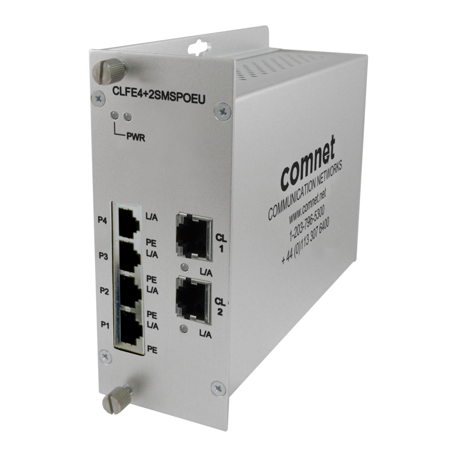
Comnet CLFE4+2SMSPOEU Руководство по установке и эксплуатации - Страница 4
Просмотреть онлайн или скачать pdf Руководство по установке и эксплуатации для Переключатель Comnet CLFE4+2SMSPOEU. Comnet CLFE4+2SMSPOEU 7 страниц. 10/100tx drop/insert/repeat 4tx/2ex self-managed switch with poe+

INSTALLATION AND OPERATION MANUAL
Installation Instructions
1 - SET DATA RATE DIP SWITCHES
Locate the 10/100 data rate DIP switch on the unit.
Set the data rate according to bandwidth required.
NOTE: The data rate must be set the same on both the local and remote units.
2 - SET WIRE PAIR DIP SWITCHES
Locate the wire pair DIP switch on the unit.
Set the pair according to number of twisted wire pairs used (1 or 4).
NOTE: The number of pairs selected must be set the same on both the local and remote units.
Figure 2 – One-Pair Pin Assignment
For 1-pair mode, use the first pair of pins (pins 1 and 2) of the
"Extended Ethernet" RJ-45 port.
3 - SET LOCAL/REMOTE DIP SWITCHES
Set the Local/Remote switch to Local (LC) for Local (head end) devices or Remote (RM) for Remote (field end) devices.
4 - SET CL1 UP LINK ENABLED DIP SWITCH
Set the Up Link switch to the "ON" position to enable Uplink port features.
5 - CONNECT EXTENDED WIRING
Connect Extended Distance Port to field wiring.
6 - CONNECT NETWORK WIRING
Using Cat5/5e, connect Local unit to network and Remote unit to camera.
7 - CONNECT POWER
Connect power to unit per the following table.
NOTE: Remove Electrical Connector for Rack Mount Units
Table 2 – Power Connections per Use Case
Operating Voltage
Use Power Connectors
Contact the ComNet Design Center, or refer to the appropriate installation and operation manual when configuring and specifying power for a deployment.
†
8 - VERIFY FUNCTIONALITY
See LED table below and Troubleshooting Guide if corrective action is needed.
Table 3 – Indicating LEDs
PWR
SOLID
Power Applied
BLINKING
–
OFF
Power Off
TECH SUPPORT: 1.888.678.9427
(UTP MODELS ONLY, FOR COAX MODELS SKIP TO STEP 3)
Non-PoE
12 to 24 VDC (9 VDC
when in C1 or C2 Rack)
†
RTN and +Vin
Link (Ethernet Port)
Link Detected
–
No Link
CLFE4+2SMS[POE](C,U) SERIES
†
Activity (Ethernet Port) L/A (CH 1 or 2)
–
Link Detected
Data Activity
Data Activity
–
No Link
PoE Models Only
48 to 56 VDC
RTN and +Vin
POE (PoE Models Only)
Supplying PoE to PD(s)
–
Not Supplying PoE to PD(s)
INS_CLFE4+2SMS[POE](C,U)_REV– 10/27/11 PAGE 4
