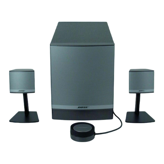
Bose Companion 3 Series II Руководство по эксплуатации - Страница 32
Просмотреть онлайн или скачать pdf Руководство по эксплуатации для Динамики Bose Companion 3 Series II. Bose Companion 3 Series II 36 страниц. Multimedia speaker system
Также для Bose Companion 3 Series II: Руководство пользователя (40 страниц), Руководство пользователя (40 страниц), Руководство пользователя (22 страниц), Руководство пользователя (10 страниц), Руководство пользователя (20 страниц), Руководство пользователя (26 страниц), Руководство по быстрой настройке (2 страниц), Руководство по быстрой настройке (2 страниц), Подробная инструкция по сборке (2 страниц), Руководство по установке (20 страниц), Технические характеристики (6 страниц), Брошюра и технические характеристики (4 страниц), Руководство пользователя (19 страниц), Руководство по эксплуатации (16 страниц)

- 1. Table of Contents
- 2. Safety Information
- 3. Electrostatic Discharge Sensitive (ESDS) Device Handling
- 4. Specifications
- 5. Part List Notes
- 6. Bass Module Assembly Parts List
- 7. Amplifier Module Assembly Parts List
- 8. Packing Parts List
- 9. Electrical Parts List
- 10. Main PCB Assembly Parts List
- 11. Power Supply PCB Assembly Parts List
- 12. Disassembly Procedures
- 13. Test Procedures
- 14. Theory of Operation
- 15. Revision History
