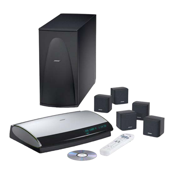
Bose Lifestyle PS48 Процедура тестирования - Страница 2
Просмотреть онлайн или скачать pdf Процедура тестирования для Динамики Bose Lifestyle PS48. Bose Lifestyle PS48 5 страниц. Digital acoustimass powered speakers
Также для Bose Lifestyle PS48: Руководство по эксплуатации (43 страниц)

PS28/48 Performance Verification Procedures
(Without AV28 Media Center Console)
Test setup procedures
Place the bass module into TAP mode using
the procedures located at the end of this
document.
Note: Place all four DIP switches into the down
position before returning the unit to the customer.
Test cable part number 264564, Figure 16, is
needed to test the bass module.
Connect the D-sub, 9 pin connector on the test
cable to the COM port on your computer.
Connect the RJ-45, 8 pin connector to the
bass module.
The bass module requires a digital audio input.
Connect the analog output of an oscillator to
the analog input of an Analog to Digital (A-D)
converter. Connect the test cable's RCA
connector to the A-D converter S/PDIF output.
1. Sweep Test
1.1 Issue the following TAP commands:
SO ALL D
(select all digital source inputs)
SP 5
(5 speaker mode)
VO CB 0
(set volume to full output, 0dB)
MU AMP OFF (unmute the amp)
1.2 Apply a 200 mVrms, 25 Hz signal to the left
and right input of the analog to digital (A-D)
converter. Listen for any extraneous noises
such as rubbing, scraping, or ticking.
Note: No extraneous noises such as rubbing,
scraping or ticking should be heard. To distin-
guish between normal suspension noise, rubs
and ticks, displace the woofer cone with your
finger. If the sound can be made to go away or
get worse, it's a rub or tick and the woofer
should be replaced. If the noise stays the
same, it's normal suspension noise and it will
not be heard with regular program material.
1.3 Sweep the bass module from 40 Hz to 300 Hz.
Listen carefully for any buzzes, rattles
or extraneous noises coming from the bass
module.
Note: Redress any wire or component that
buzzes.
2 Bass Module Air Leak Test
2.1 Apply a 200 mVrms, 40 Hz signal to the
input of the A-D converter.
2.2 Check for air leaks from the cabinet. Listen
near the areas where the plastic seals to the
wood.
3. Cube Speaker Phase Test
Note: The DC voltage should only be momen-
tarily applied to the cube speaker input to avoid
damaging the speakers.
3. 1 Observing polarity, momentarily apply 8 Vdc to
the input of the cube speaker.
3.2 The speakers should move outward with
the application of the dc voltage. Check the
cube wiring if it moves inward.
4. Cube Speaker Sweep Test
4.1 Apply an 11 Vrms, 20 Hz signal to the
input of the satellite. Change the applied signal
to 8 Vrms, 150 Hz. Sweep the oscillator from
150 Hz to 2 kHz.
4.2 Listen for rubs, ticks, air leaks, buzzes or
other extraneous noises.
Note: Defects such as rubs, ticks and air leaks
will typically be most audible during the 20 Hz
test. Defects such as buzzes will typically be
heard during the 150 Hz to 2 kHz sweep.
Note: The satellite cubes are not repairable.
®
The Jewel Cube
speakers are repairable.
5. Listening Test
5.1 Connect the cube speakers to the outputs
of the bass module.
5.2 Connect an audio source (i.e. CD player)
to the input of the A-D converter.
5.3 Perform procedure 1.1
5.4 Adjust the volume output of the audio
source to a comfortable level and listen for a
clean undistored audio output from the bass
module and cube speakers.
2
