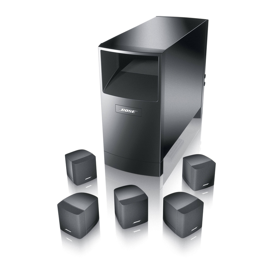
Bose Acoustimass10 Series IV Руководство пользователя - Страница 9
Просмотреть онлайн или скачать pdf Руководство пользователя для Акустическая система Bose Acoustimass10 Series IV. Bose Acoustimass10 Series IV 18 страниц. Home entertainment speaker systems
Также для Bose Acoustimass10 Series IV: Руководство пользователя (18 страниц), Руководство пользователя (16 страниц)

Connect the Acoustimass
speakers
Use the 20 foot (6 m) cable with three pairs of wires to connect the Acoustimass module to
the center and front cube speakers. Just press the custom RCA connectors in place.
1. Insert the gray connector marked C
into the gray terminal on the center
speaker.
2. Insert the black connector marked L
into the black terminal on the left front
speaker (to the left of the TV as you
face it), and the black connector
marked R to the black terminal on the
right front speaker.
3. At the Acoustimass module, check to
be sure the connectors are firmly
inserted into the proper OUTPUT TO
CUBE SPEAKER jacks.
a. Black L connector to the L jack.
b. Gray C connector to the C jack.
c. Black R connector to the R jack.
Connect the Acoustimass module to the surround cube
speakers
Use the 50 foot (15 m) cable with gray RCA connectors to join the module to the surround
speakers.
1. Insert the gray connector marked LS into the gray terminal on the left surround speaker
(on your left as you face the TV).
2. Insert the gray connector marked RS into the gray terminal on the right surround
speaker.
3. At the Acoustimass module, make sure the gray connectors are firmly inserted into the
LS and RS OUTPUT TO SPEAKER jacks.
Connect the Acoustimass module to the receiver
Use the 20 foot (6 m) cable with five wire pairs to connect the Acoustimass module to your
surround sound receiver.
1. Match the wire labels to the SPEAKER OUTPUT labels on the receiver:
a. L wires go to the Left Front SPEAKER OUTPUT connections.
b. C wires go to the Center SPEAKER OUTPUT connections.
c. R wires go to the Right Front SPEAKER OUTPUT connections.
d. LS wires go to the Left Surround (rear) SPEAKER OUTPUT connections.
e. RS wires go to the Right Surround (rear) SPEAKER OUTPUT connections.
2. Match the polarity on the receiver. Connect the wire pairs in phase (+ to + and – to –).
a. Connect each wire marked with a red collar (+) to the appropriate red (+) output.
b. Connect each plain wire (–) to the appropriate black (–) output.
3. At the Acoustimass module, check to make sure all RCA connectors are firmly inserted
into the proper INPUT FROM RECEIVER OR AMPLIFIER jacks. Black connectors go
into L and R jacks. Gray connectors go into C, LS, and RS jacks.
AM183644_01_V.pdf
module to the center and front cube
®
®
December 20, 2001
Setting Up
Figure 8
Making cube speaker
connections
CAUTION:
Do not connect the
Acoustimass module directly
to your television unless the
television provides surround
decoding circuitry and
amplified outputs for all
channels.
9
