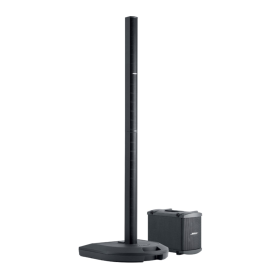
Bose Personalized Amplification System Руководство по устранению неполадок - Страница 41
Просмотреть онлайн или скачать pdf Руководство по устранению неполадок для Стереосистема Bose Personalized Amplification System. Bose Personalized Amplification System 50 страниц.
Также для Bose Personalized Amplification System: Руководство пользователя (28 страниц)

P0.1
1
P0.0
2
SDAT/P4.3
3
S3P8475
SCLK/P4.2
4
V
/V
5
DD
DD
(44-QFP)
V
/V
6
SS
SS
X
7
OUT
Top-View
X
8
IN
V
/TEST
9
PP
P4.1
10
P4.0
11
NOTE: The bolds indicate an OTP pin name.
Pin
Name
P0.0–P0.7
P1.0–P1.5
P2.0–P2.7
P3.0–P3.7
P4.0–P4.3
P4.4–P4.5
X
X
IN,
OUT
RESET
TEST
AV
REF,
AV
SS
V
V
DD,
SS
T0
T1CK
T1
BUZ
RxD
TxD
INT0-INT7
ADC0-
ADC7
APPENDIX
33
P1.4/RxD
32
P1.5/TxD
31
P3.7/ADC7
30
P3.6/ADC6
29
P3.5/ADC5
28
P3.4/ADC4
27
P3.3/ADC3
26
P3.2/ADC2
25
P3.1/ADC1
24
P3.0/ADC0
23
AV
SS
ADC0-ADC7
Pin
Pin Description
Type
I/O
Nibble-programmable I/O port for Schmitt trigger
input or push-pull, open-drain output. Pull-up
resistors are assignable by software.
I/O
Bit-programmable I/O port for Schmitt trigger input
or push-pull output. Pull-up resistors are assignable
by software. Port 1 pin can also by used as
alternative function (T0, T1CK, T1, BUZ, RxD, TxD)
I/O
Bit-programmable I/O port for Schmitt trigger input
or push-pull output. Pull-up resistors are assignable
by software. Port 2 pins can also be used as
external interrupt.
I/O
Bit-programmable I/O port for Schmitt trigger input
or push-pull output. Pull-up resistors are assignable
by software. Port 3 pins can also be used as A/D
converter by software.
I/O
Bit-programmable I/O port for Schmitt trigger input
or push-pull, open-drain output. Pull-up resistors are
assingable by software.
O
Push-pull output only
–
Crystal or ceramic oscillator signal for system clock.
I
System reset signal input pin.
I
Test signal input pin (for factory use only; muse be
connected to V
)
SS
–
A/D converter reference voltage input and ground
–
Voltage input pin and ground
I/O
Timer 0 capture input or PWM output pin
I
Timer 1 external clock input pin
I/O
Timer 1 capture input or PWM output pin
O
200Hz-20kHz frequency output for buzzer sound
I/O
UART receive and transmit input or output
O
UART transmit output
I
External interrupt input
I
A/D converter input
S3P8475 Microproccessor
P0.0-P0.7
BLOCK DIAGRAM
Basic
Port 0
Timer
X
IN
OSC
X
OUT
Port I/O and Interrupt
T0(CAP)
Timer 0
T0(PWM)
T1(CAP)
Timer 1
T1(PWM)
SAM87RC CPU
ADC
P1.4/RxD
UART
P1.5/TxD
8/16-Kbyte
ROM
BUZ
P1.3/BUZ
Circuit
Number
E
D
D
F
E
C
–
B
–
–
–
D
D
D
D
D
D
E
F
41
P1.0-P1.5
T0, T1CK, T1,
BUZ, RxD, TxD
Port 1
P2.0-P2.7
Port 2
INT0-INT7
Control
P3.0-P3.7
Port 3
ADC0-ADC7
P4.0-P4.3
272-byte
Port 4
Register
P4.4-P4.5
File
Pin
Share
Number
Pins
2-1,
–
43-38
37-32
T0, T1CK,
T1, BUZ,
RxD, TxD
13-20
INT0-
INT7
ADC0-
24-31
ADC7
11-10,
–
4-3
44, 21
–
8, 7
–
12
–
9
–
22, 23
–
5, 6
–
37
P1.0
36
P1.1
35
P1.2
34
P1.3
33
P1.4
32
P1.5
13-20
P2.0-P2.7
24-31
P3.0-P3.7
