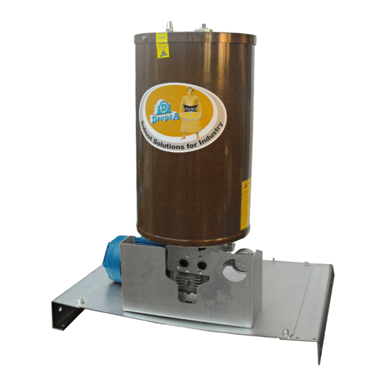
DROPSA 2487013 Руководство по эксплуатации и техническому обслуживанию - Страница 10
Просмотреть онлайн или скачать pdf Руководство по эксплуатации и техническому обслуживанию для Водяной насос DROPSA 2487013. DROPSA 2487013 18 страниц.

7.2.1 LASER PROBE SETTING, 24V CC OUT NO E NC (1 threshold)
1. Reference notch.
2. Yellow led: lights when the set value is reached,
(outlet=ON).
3. Lock ring.
4. Setting lock ring (be adjusted manually after unlocking).
5. Green led: indicates the correct power supply (24V cc).
* To obtain a correct setting bring the lock ring to maximum setting value and then down to desire value.
On the pump is placed a label that shows the wiring diagram and setting values. The pump is normally equipped with pre setting
sensor to "L" thresholds (minimum level). Whereas other thresholds: MM (absolute maximum level), M (absolute level), LL
(absolute minimum level), can be set by the user.
Attention you can only set one thresholds at a time
7.2.2 Procedure for calibrating the capacitive probe nc (optional)
Before being assembled the capacitive probe must be calibrated in accordance with the following sequence:
1. connect the sensor electrically;
2. immerse the sensor in the lubricant, down to half of its length;
3. remove the sensor from the lubricant until it skims the surface of the lubricant;
4. at this point there can be two possible types of operation:
-
If its status does not change its sensitivity must be reduced (by acting on the screws for adjusting sensor sensitivity) until its
state of excitation is reached.
-
if its status changes, the sensor already possesses the correct sensitivity
5. after checking that the sensor has been correctly read, the sensor reading must be repeated at least three times
6. Tighten the capacitive probe on the probe carrier rod, complying with the following assembly height:
-
450 mm (from below the cover up to the lower surface of the sensor) for a 30 kg tank
-
900 mm (from below the cover up to the lower surface of the sensor) for a 100 kg tank.
Operating instructions for the capacitive probe (model Sc30sp-a20 no)
20 ÷ 250 AC
I= 500 mA
Sensors in version with alternate current (2 wires)
10
BLUE
YELLOW/GREEN
BROWN
