DROPSA 3135132 Руководство по эксплуатации и техническому обслуживанию - Страница 3
Просмотреть онлайн или скачать pdf Руководство по эксплуатации и техническому обслуживанию для Системы смазки DROPSA 3135132. DROPSA 3135132 14 страниц. Chain lubrication & dispensing

5. COMPONENTS
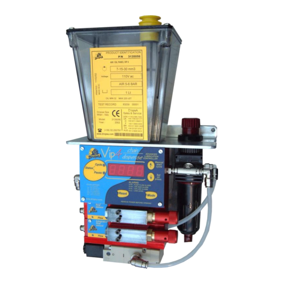
Main Unit Vip4chain
Vip4chain Electronic Controller : Controls and monitors all the components on the unit, including chain
impulses, air pressure, oil flow, pump activations and oil level.
Pneumatics Circuit: A pressure regulator and filter allows the user to fine tune the air jet to the lubrication
point.
An
integrated
A solenoid valve is used to activate the micropumps at the desired intervals.
Oil Reservoir: A Clear 1 litre reservoir.
Pneumatic micropumps.
The micropumps are installed on the air/oil mixing bases. They are adjustable from 0 to 30 mm³ per cycle. To
increase the flow turn the pump adjusting dial clockwise, to decrease counterclockwise.
Modular mixing sub-base with flow sensing.
The modular base has two functions.
Firstly, it monitors that the pumps have correctly injected oil into the unit via a displacement sensor and
secondly, it injects the oil into an air stream to be carried to the lubrication point.
No settings are required as the unit automatically configures itself. A green LED will indicate the correct
operation of the pump module fitted on top of the base unit.
The signals are then sent back to the Main Vip4chain Controller to determine that all the units are
functioning correctly.
When a lubrication cycle is in progress, the LED on the sub base indicates the flow of oil from the micropumps. During
the standby interval the LED will remain off
Item
PART
NUMBER
1
3044335
2
3130139
3
3155148
4
3155149
5
1524408
6
3103116
7
1639118
8
1639119
air
pressure
1
5
6
Reservoir
Filling Cap & Filter
Solenoid 24V DC
Solenoid 110V AC
Modular Mixing Sub-Base
Adjustable pneumatic Micropump
Wiring Box , 24V Version
Wiring Box, 110V Version
transducer
can
monitors
2
3 o 4
DESCRIPTION
min/max
air
pressures.
7 o 8
3
