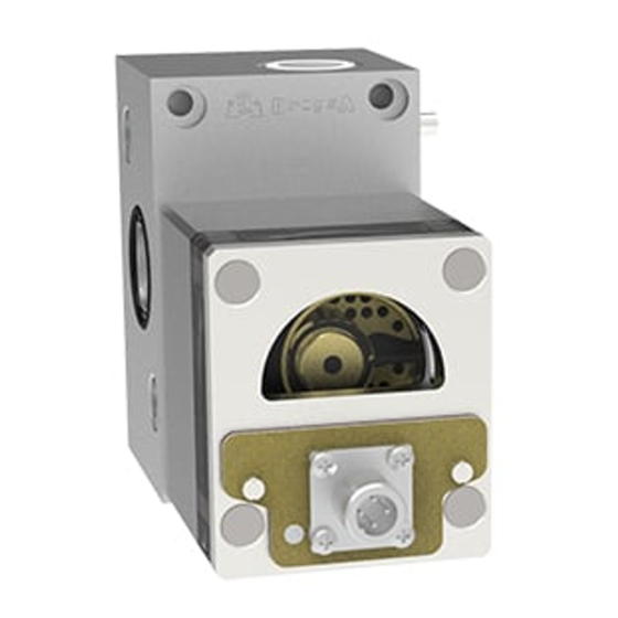
DROPSA 1525700 Руководство по эксплуатации и техническому обслуживанию - Страница 6
Просмотреть онлайн или скачать pdf Руководство по эксплуатации и техническому обслуживанию для Измерительные приборы DROPSA 1525700. DROPSA 1525700 8 страниц. Volumetric flow meter for controlling the flow of liquids

11.4 PART NUMBER
FITTING WITH NUTS AND RING
Ø tube
Part Number
mm
in.
10
0,39
92374
12
0,47
92375
16
0,62
92376
J
3
1
2
9
9A
X
Fig.1
BY-PASS version
POS.
1
Grub screw
2
screw
3
Base completed with adjustment screw(X), by-pass (Y), grub (pos. 1), screws (pos. 2), O-Ring (pos. 4,12,9,9A,13,13A)
3A
Base complete with regulation screw (X), grub screws (pos. 1), screws (pos. 2), O-Ring (pos. 4,12,9,9A,13,13A)
4
O-Ring in Viton
5
Gasket
6
Plug - Threads G 1/4 UNI-ISO 228/1
7
Screw for metering module 5 cm³ (0,3 cu.in.)
7a
Screw for metering module 20 cm³ (1,22 cu.in.)
8
Optical sensor
9
O-Ring for adjustment valve
9a
O-Ring for adjustment valve
10
Metering module "A" 5 cm³ (0,3 cu.in.) completed with screws pos. 7
10a
Metering module "B" 20 cm³ (1,22 cu.in.) complete d with screws pos. 7a
*
O-Ring in Viton for Metering module
11
Screw
12
O-Ring in Viton
13
O-Ring for by-pass valve
13A O-Ring for by-pass valve
14
Spring for non-return valve
15
ball for Non-return valve
X
Flow regulating screw set
Y
By-pass valve assembly
* O-Ring is built-in for 10 module.
O-Ring Pos. 4 must be mounted only between base and base.
Screws (Pos. 11), Gasket (Pos. 5) and Plug (Pos. 6) must be ordered separately.
6
FITTING WITH NUTS AND RING
Ø tube
mm
in.
8
0,31
10
0,39
12
0,47
K
14
15
12
13
13a
10
Y
DESCRIPTION
FITTING WITH CHECK VALVE, NUTS AND RING
Part Number
Ø tube
mm
92363
8
92270
10
92254
12
3A
4
7
8
Version without BY-PASS
Part Number
in.
0,31
92368
0,39
92369
0,47
92370
11
6
5
7a
10a
PART N°ALUMINIUM Q.TY
1523343
0014094
1525702
1525720
0058390
3190318
3234206
0021776
0021777
1639198
0018805
0061103
1525704
1525732
1523353
0014084
1523349
0018912
0018807
0281017
0020507
1525711
1525708
2
2
1
1
1
1
1
4
4
1
1
1
1
1
1
2
2
1
1
1
1
1
1
