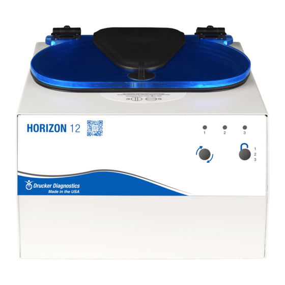
Drucker Diagnostics Horizon 12 Руководство по эксплуатации - Страница 6
Просмотреть онлайн или скачать pdf Руководство по эксплуатации для Лабораторное оборудование Drucker Diagnostics Horizon 12. Drucker Diagnostics Horizon 12 12 страниц.

7.6. Removing the Cabinet (Upper Housing)
•
There are eight screws that fasten the centrifuge cabinet to the base.
•
Begin by unplugging the centrifuge.
•
Use a 3/32 hex key to remove the cabinet screws (three on left and right sides, two
in the rear)
•
The cabinet control panel is attached to the base internally with cable harnesses.
Be careful not to stress the cables when removing the cabinet.
•
Stand directly in front of the centrifuge and lift the cabinet straight up and off the
base, setting it down on its right side.
•
Gently remove the power supply and motor harnesses from the PCB.
7.7. Replacing the Lid Lock Assembly
•
The lid tray assembly is accessible once the cabinet has been removed.
•
Gently remove the lid tray wire harness from the PCB.
•
The lid tray assembly is held in place with two #6 Nylok nuts. Use a 5/16" nut driver
to remove the nuts. The tray will slide off the threaded studs.
•
To install the lid tray, slide it onto the studs, and secure it with two #6 Nylok nuts,
hand tight.
•
Complete the installation by gently plugging the wire harness into the PCB header
'J2'. The header and connector are keyed for proper orientation.
7.8. Replacing the PCB
•
The PCB is accessible once the cabinet has been removed. Make certain that all
wire harnesses have been disconnected. Use standard precautions for handling
static sensitive components.
•
The PCB is held in place with six #6 Nylok nuts and plastic insulator washers. Use a
5/16" nut driver to remove the nuts. The PCB and washers are now free to slide off
the threaded studs.
•
Beneath the PCB are six plastic standoffs. If they are crushed, replace them before
reassembly.
•
To install the PCB, make certain that six plastic standoffs are present on the control
panel studs.
•
Slide the board onto the studs
•
Install six plastic washers onto the studs securing the circuit card.
•
The six nuts should be tightened only until the buttons on the control panel click
when pressed – do not over tighten. Each nut sets the height of a separate control
panel button. Too low, and they cannot be actuated, too high and they jam against
the front panel label and are always in the 'ON' state. Tighten each nut a ¼ turn in
succession, trying each corresponding button as you go.
•
Once each control panel button clicks when pressed, installation is complete.
DRUCKER DIAGNOSTICS
HORIZON 12 SERVICE MANUAL
SM015
REV A
6
