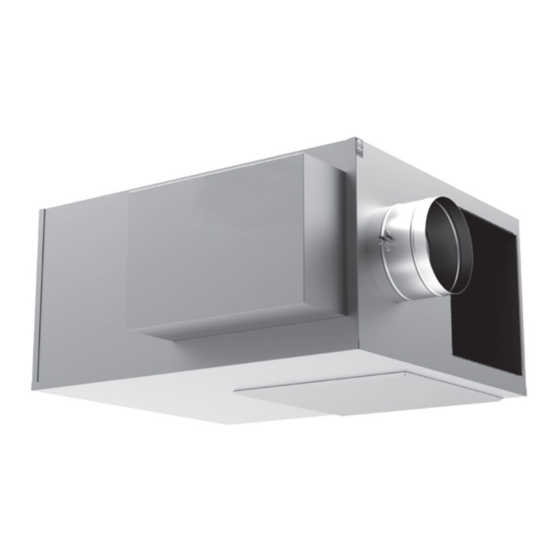
Daikin MQFVI5 Руководство по установке и обслуживанию - Страница 4
Просмотреть онлайн или скачать pdf Руководство по установке и обслуживанию для Вентилятор Daikin MQFVI5. Daikin MQFVI5 12 страниц. Parallel fan powered variable air volume (vav) terminal box

Receiving Inspection
Do not use the flow sensor, connecting tubing, or damper
shaft as a lift point. Damage to the flow sensor or controls
may result.
Prior to removing the shipping material, visually inspect
the packing materials. There should be a black plastic strip
wrapped in the clear plastic shrink wrap. If this black plastic
strip is missing, the shipment may have been repacked by
the shipper and you should make note of this on the shipping
documents and inform the delivering carrier. After unpacking
the terminal, check it for shipping damage. If any shipping
damage is found, report it immediately to the delivering
carrier. Store units in a clean, dry location prior to installation.
Units with controls are not recommended for use in ambient
temperatures greater than 95°F. For protection of controls, do
not store in ambient temperatures greater than 135°F.
IM 1102 • PARALLEL TERMINAL BOX
CAUTION
Hanging/Installation Requirements
If equipped with pneumatic controls, the orientation of the
terminal is critical. The pneumatic controls must be mounted
right side up. The fan powered unit must be level within +
or – 10 degrees of horizontal, both parallel to the air flow and
at the right angle of air flow. The control side of the terminal
is labeled with an arrow indicating UP. Unless otherwise
noted, most analog and digital controls may be installed in
any orientation.
Check with the local Daikin representative for verification.
The equipment is heavy and mounted in the ceiling. Use
caution and follow OSHA or SMACNA installation guidelines.
The Fan Powered Air Terminal should be suspended from the
building structure in a horizontal plane with the two bottom
access panels facing downward. Do not obstruct the bottom
access panels or control panel enclosure cover. At both
ends of the air terminal unit, a three inch wide mounting lip
provides easy installation of either trapeze type hangers or
hanging straps.
• Use the required mounting support method prescribed for
the rectangular duct per the job specifications, or
• Use hanging straps located at both ends of the fan
powered unit
(Figure
• Use trapeze mounts located at both ends of the fan
powered terminal unit
• Fan powered air terminals may be suspended with
optional hanging brackets and hanger rod.
The Fan Powered Air Terminal is not suitable for outdoor use.
4
I
nsTallaTIon
CAUTION
CAUTION
1), or
(Figure
2), or
(Figure
www.DaikinApplied.com
I
nsTallaTIon
3)
