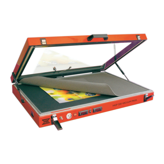
Drytac HOT PRESS HGP360 Руководство пользователя - Страница 5
Просмотреть онлайн или скачать pdf Руководство пользователя для Электроинструмент Drytac HOT PRESS HGP360. Drytac HOT PRESS HGP360 19 страниц. Heated glass top vacuum press
Также для Drytac HOT PRESS HGP360: Руководство по эксплуатации (19 страниц)

HOT PRESS USERS MANUAL
stand. Undo catches at front of press and raise lid. Remove three screws
at front of diaphragm and draw diaphragm forward by approximately
300 mm or 12 inches. Working on underside of diaphragm, remove
hoses from fi ttings on diaphragm by pushing collar on hose end of fi tting
inwards and pulling out hose. Remove diaphragm from press. Using the
4 M6 x 80 mm bolts, 8 M6 penny washers, 4 M6 spring washers and 4
M6 nuts, secure the press to the stand by passing the bolts up through
the holes in the stand ends and into the base of the press. Tighten these
nuts and bolts. Insert the diaphragm back into the press and unsert the
hoses back into the fi ttings on the underside of the diaphragm.
Push the diaphragm back into position ensuring it fi ts into the three
clips at the back of the press and re-fi t the three screws at the front of
the diaphragm.
Stand Assembly Instructions for Small Models
(HGP220 / 260/ 36
0)
Component list:
• 2 x leg assemblies
• 2 x top rails
• 2 x bottom rails
• 12 x rail bolts (16 x for 360) M8 x 60 mm dome head
• 4 x press fi xing bolts M6 x 80 mm cap head
• 4 x penny washers ¼ x 1 "
• 4 x shakeproof washers M6
• 1 x M6 Allen key
Loosely fi t the top rails to the top of the leg assemblies to form a rectangle,
using 8 of the M8 x 60 mm bolts. Loosely fi t the bottom rails, about half
way up the leg assemblies, using the remaining M8 x 60 bolts. Tighten
all bolts using the Allen key and ensure stand is steady. The top rails are
inset from the front and rear, the largest inset is the front of the stand. Lift
press onto stand. Fit M6 x 80 mm bolts with shakeprooof washers, then
with the penny washers, then insert them up through the leg assemblies
into the base of the press. Tighten press fi xing bolts using the Allen key,
until rubber press feet are compressed slightly.
Connecting the Vacuum Pump
A length of plastic vacuum tubing (either red or green, depending on
the model) is supplied with the equipment. Connect one end to the
pump and the other end to the rear of the vacuum press. No tools are
needed - the tubing is a simple "push fi t" into the special connectors.
You will feel two stages of resistance as the tube is inserted. The ends
of the tubing must be clean and smooth to ensure a good seal. If
damaged, simply cut off 1/4" (5mm) with a sharp knife. To remove the
tubing, press the end of the metal fi tting and pull the tubing out.
Plug the electrical cord from the pump into the matching connector on
the rear of the vacuum press.
SHOULD BE CARRIED
THE CORRECT FUNCTIONING OF
YOUR VACUUM PRESS CANNOT
BE GUARANTEED IF THE PRESS
IS NOT MOUNTED SECURELY
AND THE PRESS
Illustration 5A: Vacuum pump
connections .
5
Press Set Up
WARNING
THIS OPERATION
OUT BY A MINIMUM
OF SIX PEOPLE.
WARNING
ONTO THE STAND
LEVELLED.
