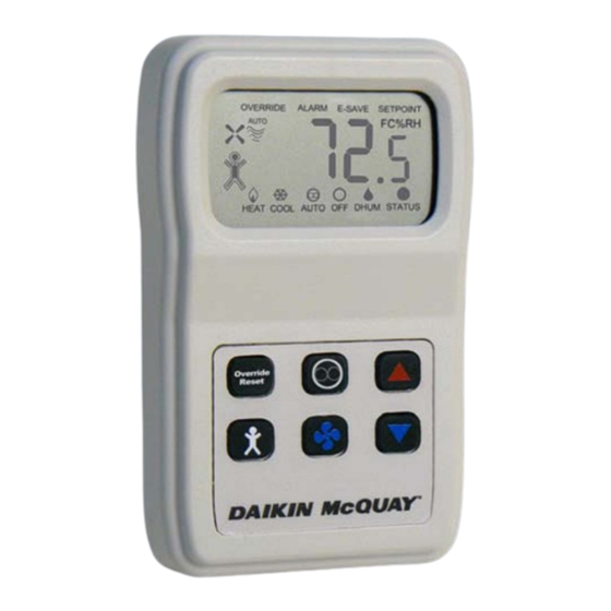
Daikin McQuay 910113679 Данные по установке и обслуживанию - Страница 2
Просмотреть онлайн или скачать pdf Данные по установке и обслуживанию для Аксессуары Daikin McQuay 910113679. Daikin McQuay 910113679 16 страниц. Digitally adjustable display sensor for water source heat pumps smartsource gs series; smartsource gt series; with microtech iii controls enfinity cch series; enfinity ccw series; enfinity vfc series; enfinity vfw series; enfinity lvc series; enfinity lvw

Contents
Overview...............................................................................3
Applications .........................................................................4
Sensor Functions ................................................................5
910113679, Fan Coil Unit Model: .....................................5
910121754, Water Source Heat Pump Model: .................5
Sensor Dimensions .............................................................5
Terminations ........................................................................6
Mounting ..............................................................................7
Location ............................................................................7
Junction Box, (J-Box)........................................................7
Drywall Mounting ..............................................................7
Maintenance .........................................................................7
Terminal Descriptions .........................................................7
Initial Start-Up Occupied Sequence: .................................8
Power Fail Start-Up Occupied Sequence: .........................8
Display Descriptions ...........................................................8
Numerical Display .............................................................8
Adjusting The Setpoint (Temperature or Humidity) ...........8
Occupied Icon Indicator: ...................................................8
The Word "Override" On The Display: ..............................8
Fan Status & Speed Indicators: ........................................9
Alarm Word On The Display: ............................................9
E-Save Word On The Display: ..........................................9
Setpoint Word On The Display: ........................................9
Status Word & Dot On The Display: .................................9
Front Panel Button Operation ..........................................10
System Mode Indication (FCU Only) ................................10
"Heat/Cool/Auto/Off" .......................................................10
Fan Speed Indication (FCU Only) .....................................10
"Auto/High/Medium/Low" ................................................10
System Mode Indication (WSHP Only) ............................10
"Heat/Cool/Auto/Off/Dhum" .............................................10
Page 2 of 16 / IM 1171-3
Fan Indication (WSHP Only) .............................................10
"Auto/On" ........................................................................10
Override/Reset Button (Timed ...........................................
Override & Alarm Reset): ................................................10
Occupied Button (Occupied/ .............................................
Unoccupied Request): ...................................................10
Up & Down Setpoint Buttons .............................................
(Temp Or Humidity): ....................................................... 11
(WSHP Has Heat/Cool/Auto/Off/Dhum): ........................ 11
Fan Mode Button (FCU Has Auto/.....................................
High/Medium/Low/Off) (WSHP Has ..................................
Auto/On):........................................................................ 11
Optional Technician Adjustments ....................................11
Order) ............................................................................. 11
Label Description Setting ................................................ 11
Program Mode Menu Pages: (Display Required) ........... 11
Entering Program Mode And Making Changes: ............. 11
Program Mode Menu Pages: .......................................... 11
Diagnostics ........................................................................14
Problem & Possible Solution ..........................................14
Specifications ....................................................................15
Supply Voltage: ...............................................................15
Sensor: ...........................................................................15
Outputs: ..........................................................................15
Sensor Controls: .............................................................15
Field Setup Jumper J50: .................................................15
Display: ...........................................................................15
Field Configuration Menu: ..............................................15
Enclosure Material: .........................................................15
Ambient:..........................................................................15
Agency: ...........................................................................15
