ATS Co-Pilot Руководство по установке - Страница 9
Просмотреть онлайн или скачать pdf Руководство по установке для Автомобильные аксессуары ATS Co-Pilot. ATS Co-Pilot 12 страниц. For dodge cummins 2003
Также для ATS Co-Pilot: Руководство по установке (15 страниц), Руководство по установке (12 страниц)
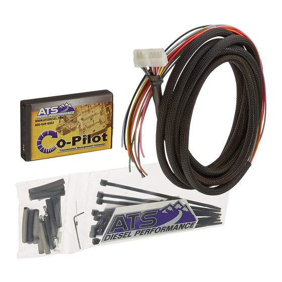
Wiring The Co-Pilot For 1997 models E350 models
Red Wire (12volts)-Pin #1
Locate the Red wire coming from the vehicle's PCM Pin #71. Tap this wire with the red
Co-Pilot wire by soldering. Shield the tap from the elements.
Black Wire- Ground (GND) – PIN #9
Locate the Black wire coming from the vehicle's PCM Pin #51. Tap this wire with the black
Co-Pilot wire by soldering. Shield the tap from the elements.
Green Wire- Vehicle Speed Sensor (VSS) – PIN #17
Locate the VSS (Vehicle Speed Sensor) wire. This Gray w/ Black stripe wire can be found at
the PCM at pin #58 Run the green wire from the Co-Pilot module to the VSS wire and cut off
any excess, but leave some slack. Solder the Green Co-Pilot wire to the VSS wire and protect
from elements, this is the most common install problem with wiring