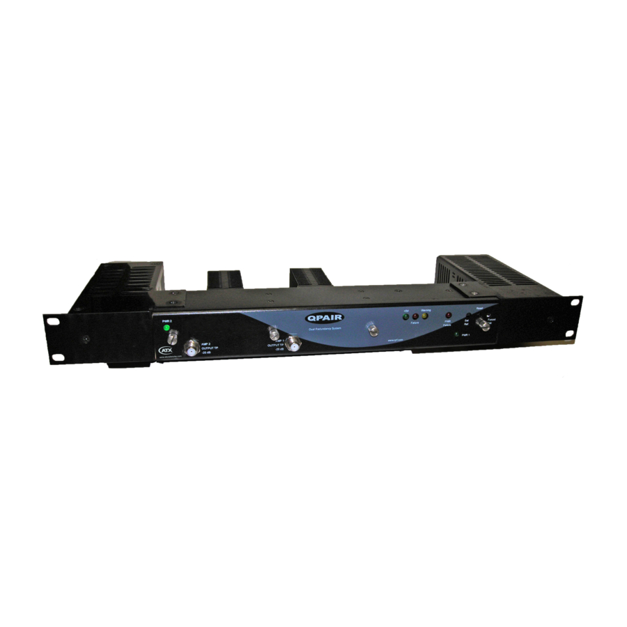
ATX Q series Руководство по установке и эксплуатации - Страница 15
Просмотреть онлайн или скачать pdf Руководство по установке и эксплуатации для Усилитель ATX Q series. ATX Q series 18 страниц. Qpair redundancy switch amplifier system

SPECIFICATIONS
4.
Specifications
4.1
Amplifier Specifications
(1)
PART NUMBER
QPAIR870-13G/*
QPAIR870-17G/*
QPAIR870-19GP/*
QPAIR870-23GP/*
QPAIR1000-13G/*
QPAIR1000-17G/*
QPAIR1000-19GP/*
QPAIR1000-23GP/*
QPAIR870-19GPH/*
QPAIR1000-19GPH/*
QPAIR1000-23GPH/*
NOTES:
(1) /* = Denotes the type of power supply: AC, 48, or AC/48
(2) Gain specified at highest frequency.
(3) Distortions measured with 50-550 MHz analog CW (6 MHz spacing) and 550-1000 MHz noise at -6 dBc (average power per 6 MHz).
(4) Specified with 0 dB plug-in attenuators and 0 dB plug-in EQs.
(5) DC load current at +24 VDC per module.
(6) PP = Push-Pull; PD = Power-Doubled; GaAs = Gallium Arsenide; PDH = Power-Doubled High-Current
Operating temperature: 0°C to +50°C (+32°F to +122°F)
Humidity: 20-55% (without condensation)
Dimensions: 1.75"H x 19.0"W x 5.0"D (4.45H x 48.26W x 12.7D cm)
Weight: 4.6 lbs (2.1 kg)
4.2
Switch Specifications
SPECIFICATIONS
SWITCHING TIME
ISOLATION
INSERTION LOSS
RETURN LOSS
RF SENSITIVITY RANGE
POWER DISSIPATION
Q-Series
Amplifiers – QPAIR Redundant Amplifier System – Installation & Operation Manual
®
GAIN
GAIN/SLOPE CONT.
Gain
(2)
BW
Gain
Slope
Flat.
(MHz)
(dB)
(dB)
(±dB)
40-870
13
-1/+.5
.35
Pad
40-870
17
-1/+.5
.35
Pad
40-870
19
-1/+.5
.35
Pad
40-870
23
-1/+.5
.5
Pad
40-1000
13
-1/+1.5
.5
Pad
40-1000
17
-1/+1.5
.5
Pad
40-1000
19
-1/+1.5
.5
Pad
40-1000
23
-1/+1.5
.75
Pad
40-870
19
-1/+1.5
.5
Pad
40-1000
19
-1/+1.5
.5
Pad
40-1000
23
-1/+1.5
.75
Pad
100ms default delay - contact ATX for different delay times
55 dB from 40-550 MHz; 50 dB from 550-1000 MHz
2 dB (1 dB on the input and 1 dB on the output)
18 dB (min)
+20 dBmV to +50 dBmV amplifier output monitoring
6.3 watts normal mode, 8.5 watts in backup mode
I/O
CURRENT
OUTPUT
T.P.
Slope
RL
(dB)
(dB)
Plug-in
EQ
20 +/- 1
16
EQ
20 +/- 1
16
EQ
20 +/- 1
16
EQ
20 +/- 1
16
EQ
20 +/- 1
16
EQ
20 +/- 1
16
EQ
20 +/- 1
16
EQ
20 +/- 1
16
EQ
20 +/- 1
16
EQ
20 +/- 1
16
EQ
20 +/- 1
16
CHAPTER 4: SPECIFICATIONS
(3)(4)
(5)
DISTORTIONS
Level
Slope
CTB
CSO
(mA)
(dBmV)
(dB)
(-dB)
(-dB)
260
40
0
78
75
260
40
0
78.2
75.1
375
40
0
77
73
375
40
0
77
73
260
40
0
78
75
260
40
0
78
75
375
40
0
77
73
375
40
0
77
73
440
40
0
82
77
440
40
0
81
75
440
40
0
81
75
NOISE
AMP
FIGURE
(6)
TECH
(dB)
3.8
PP GaAs
4
PP GaAs
5
GaAs PD
4
GaAs PD
3.8
PP GaAs
4
PP GaAs
5
GaAs PD
4
GaAs PD
5
GaAs PDH
5
GaAs PDH
4
GaAs PDH
4-1
