3onedata TNS5500D Series Краткое руководство по эксплуатации - Страница 3
Просмотреть онлайн или скачать pdf Краткое руководство по эксплуатации для Переключатель 3onedata TNS5500D Series. 3onedata TNS5500D Series 5 страниц. 12-port series layer 2 wall mounting industrial ethernet switch
Также для 3onedata TNS5500D Series: Руководство по быстрой установке (4 страниц), Руководство по быстрой установке (4 страниц), Руководство по быстрой установке (3 страниц)
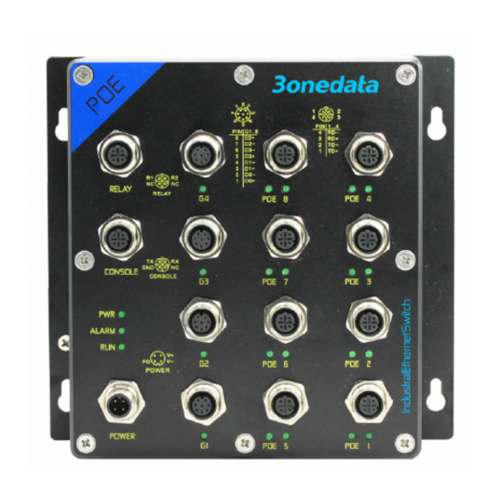
This series of device provides 8
10/100Base-T(X) interfaces, the
interface type is M12 D-Coded
4-Pin slot (female). Single port
supports up to 30W PoE power
output, PoE power supply Pin 1
and 3 are positive, 2 and 4 are negative, and M12 pin is defined
as follows:
Pin No.
Pin Definition
Description
1
TD+
Positive send data of 100M
Ethernet
2
RD+
Positive receive data of
100M Ethernet
3
TD-
Negative send data of
100M Ethernet
4
RD-
Negative receive data of
100M Ethernet
Gigabit M12 interface
This series of device provides 4 10/100/1000Base-T(X)
interfaces, the interface type is M12 X-Coded 8-Pin slot
(female). Two groups of Bypass interfaces are supported, in
which G1 and G2 are a group and G3 and G4 are a group.
The pin definitions of M12 are shown as follows:
Pin No.
Pin Definition
Description
1
GE0+
Positive bi-directional
data of Gigabit Ethernet
group 1
Pin No.
Pin Definition
Description
2
GE0-
Negative bi-directional
data of Gigabit Ethernet
group 1
3
GE1+
Positive bi-directional
data of Gigabit Ethernet
group 2
4
GE1-
Negative bi-directional
data of Gigabit Ethernet
group 2
5
GE3+
Positive bi-directional
data of Gigabit Ethernet
group 4
6
GE3-
Negative bi-directional
data of Gigabit Ethernet
group 4
7
GE2-
Negative bi-directional
data of Gigabit Ethernet
group 3
8
GE2+
Positive bi-directional
data of Gigabit Ethernet
group 3
【Checking LED Indicator】
The series of devices provide LED indicators to monitor its
operating status, which has simplified the overall
troubleshooting process. The function of each LED is
described in the table below:
LED
Indicate Description
P1/2 is connected and running
ON
normally
P1/P2
P1/2 is disconnected and
OFF
running abnormally
ON
Port link has alarm
ALM
OFF
Port link has no alarm
The device is powering on or
ON
the device is abnormal.
The device is powered off or the
RUN
OFF
device is abnormal.
Blinking 1 time per second,
Blinking
system is running normally
Ethernet port has established a
ON
valid network connection
LINK(E1-
Ethernet port
Blinking
E12, G1-
network status
G12)
Ethernet
OFF
established
connection
POE(E1-
ON
POE port is powering other PD
E8, G1-G8)
devices normally
OFF
POE port is not powering other
PD devices
【Logging in to WEB Interface】
This series of devices supports WEB management and
configuration, and computers can access devices through
Ethernet interfaces. The way of logging in to device's
configuration interface via IE browser is shown as below:
Configure the IP addresses of computer and the
device to the same network segment, and the
network between them can be mutually accessed.
Enter device's IP address in the address bar of the
computer browser.
Enter device's username and password in the login
window as shown below.
is in an active
port
has
not
valid
network