3onedata GW1108 Series Руководство по быстрой установке - Страница 3
Просмотреть онлайн или скачать pdf Руководство по быстрой установке для Шлюз 3onedata GW1108 Series. 3onedata GW1108 Series 5 страниц. Modbus gateway
Note Before Mounting:
Don't place or install the device in area near water or
moist, keep the relative humidity of the device
surrounding between 5%~95% without condensation.
Before power on, first confirm the supported power
supply specification to avoid over-voltage damaging the
device.
The device surface temperature is high after running;
please don't directly contact to avoid scalding.
【Wall-mounted Device Mounting】
Model I
Step 1
Adopt M3 screw to install the left/right mounting
board on the device backboard.
Step 2
Place the device on the wall as reference or
reference installation dimension; mark 2 bolt
positions on the wall.
Step 3
Attach the equipment to the marked wall and
tighten it with M4 screws to the marked position.
Mounting ends.
Model II
Model III
Step 1
Adopt M3 screw to install the left/right mounting
board on the device backboard.
Step 2
Place the device on the wall as reference or
reference installation dimension; mark 2 bolt
positions on the wall.
Step 3
Nail M4 screws on the wall and keep 2mm
interspace reserved.
Step 4
Hang the device on two screws and slide
downward, then tighten the screw to enhance
stability, mounting ends.
【Wall-mounted Device Disassembling】
Step 1
Device power off.
Step 2
Unscrew the screw on the wall about 2mm.
Step 3
Lift the device upward slightly; take out the device,
disassembling ends.
Note before powering on:
Power ON operation: First insert the power supply
terminal block into the device power supply interface,
and then plug the power supply plug contact and power
on.
Power OFF operation: first unpin the power plug, then
remove the power line, please note the operation order
above.
【Power Supply Connection】
9~48VDC power supply
Model I of this series provides 2-pin 5.08mm pitch
terminal block, power supply range: 9~48VDC
12~48VDC power supply
The model II and model III of this series provide
3-Pin 5.08mm pitch terminal blocks, in which V+
and V- are DC input, FG is the power grounding
input; The power supply supports non-polarity, power supply
range: 12~48VDC.
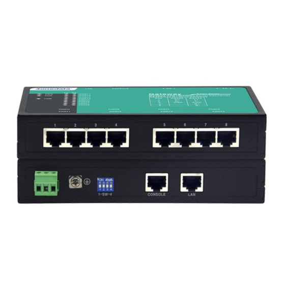
【DIP Switch Settings】
The model II and model III of this series provide
4-bits DIP switch for function setting, where "ON" is
enable valid terminal. The device needs to be powered on
again to change the status of DIP switch.
DIP switches definition as follows:
DIP
Definition
Operation
1
Reserved
-
2
Restore factory defaults
Set the DIP switch to
ON, power on the device
again, it will restore to
factory settings, then
turn off the DIP switch.
3
Reserved
-
4
Reserved
-
【Serial Port Connection】
RS-232 Interface
The model I of this series provides RS-232 port,
1
8
adopts RJ45 connector. The PIN definition as
.
follows
PIN
1
2
3
4
5.
RS-232 TXD RXD RTS CTS DSR GND DTR DCD
3IN1 Interface
The model II of this series provides 3IN1 serial
port, which supports RS232, RS485 and RS422
.
6
7
8