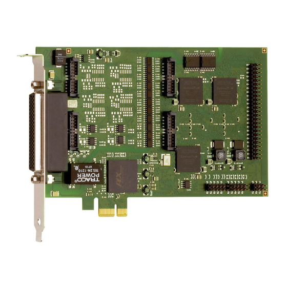
Addi-Data APCI-1710 Руководство - Страница 7
Просмотреть онлайн или скачать pdf Руководство для Компьютерное оборудование Addi-Data APCI-1710. Addi-Data APCI-1710 13 страниц. Multifunction counter board, optically isolated
Также для Addi-Data APCI-1710: Описание функций (17 страниц), Описание функций (15 страниц)

Function description
1.2 Block diagram
1.3 Used signals
With each function module, the "Pulse counter" function uses four inputs (A to D) and one output (H).
Signal
name
Counter0_x+/-
Counter1_x+/-
Counter2_x+/-
Counter3_x+/-
DigOut0_x
x = Number of the function module (0-3)
* 24 V with 24 V board version
www.addi-data.com
Fig. 1-1: Block diagram: "Pulse counter" function
Table 1-1: Used signals
Pin name
Signal type
Ax+/-
Differential/TTL/24 V*
Bx+/-
Differential/TTL/24 V*
Cx+/-
Differential/TTL/24 V*
Dx+/-
Differential/TTL/24 V*
Hx
24 V / optional 5 V
Counter 0 input
Counter 1 input
Counter 2 input
Counter 3 input
Digital output of counter 0
7
PCI-1710: Pulse counter
Function
