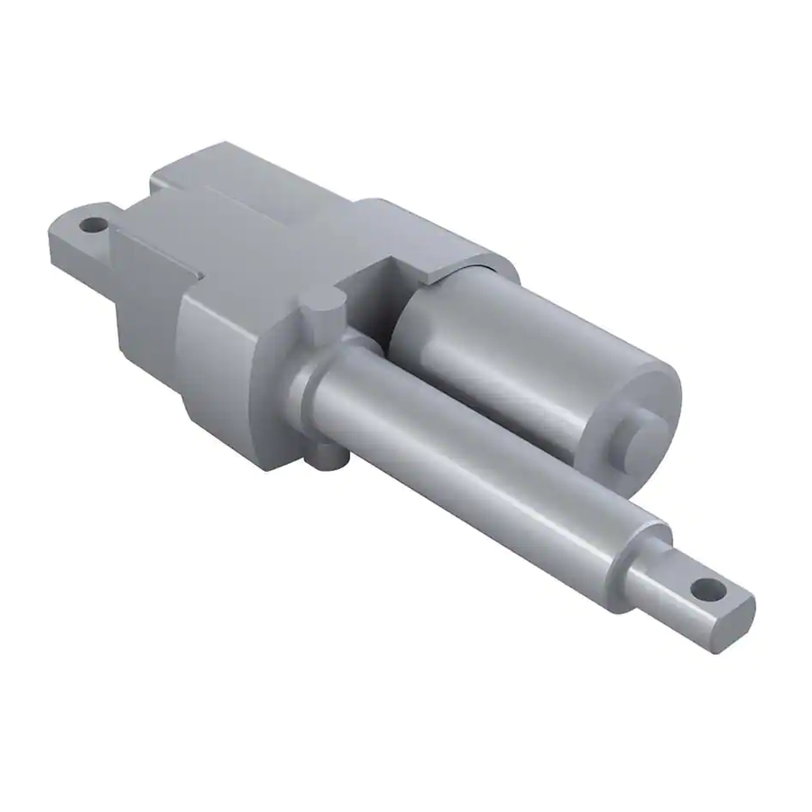
Duff-Norton 6415 Series Руководство по установке, эксплуатации и техническому обслуживанию - Страница 14
Просмотреть онлайн или скачать pdf Руководство по установке, эксплуатации и техническому обслуживанию для Контроллер Duff-Norton 6415 Series. Duff-Norton 6415 Series 16 страниц. Electromechanical linear actuators

6-1. Brake Alignment
Figure 6-1A. Brake, Spring, Motor and
Pinion Coupling Alignment
6-2. Limit Switch Wiring Diagram
Figure 6-2. Limit Switch Wiring Diagram, 6415 & 7415 Series AC Actuator
6-3. Limit Switch Assembly
Figure 6-3. Limit Switch Assembly, 6415 & 7415 Series AC Actuator
Section VI
Technical Illustrations
Figure 6-1B. Brake Spring, Motor and
14
Pinion Coupling Alignment
** Motor lead wire (red)
*
small terminal
Motor lead wire
(blue) small terminal
