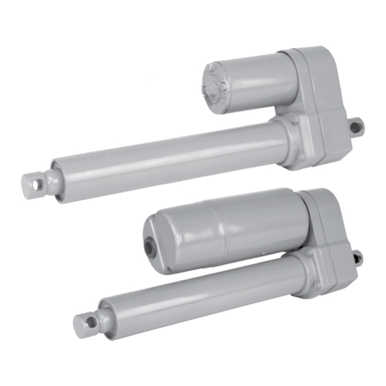
Duff-Norton TAL10-1A20 Series Инструкции по установке, эксплуатации и техническому обслуживанию - Страница 5
Просмотреть онлайн или скачать pdf Инструкции по установке, эксплуатации и техническому обслуживанию для Контроллер Duff-Norton TAL10-1A20 Series. Duff-Norton TAL10-1A20 Series 12 страниц.

Figure 2-2. Terminal Block Connections (AC)
Figure 2-3. Wiring Schematic DC with Clutch
DC models with clutch may be operated through re-
lays or by utilizing a momentary action, Double Pole,
Double Throw, Center-off toggle switch (Duff-Norton part
EM534). If actuator runs opposite the desired direction,
reverse the red and black motor wires.
2-4. Limit Switch Adjustment
1. With translating tube unrestrained, run the actuator
toward the retracted position until the switch cam
actuates the switch.
2. Rotate the translating tube by hand to the desired
retracted position.
3. With the translating tube restrained against rotation,
run the actuator to the desired extended position.
To avoid electric shock hazard and possible electrocu-
tion, disconnect power before making any adjustments
inside motor cover.
4. Disconnect power. Remove motor cover. On
Potentiometer models only: remove two screws
holding the terminal block plate and pull plate and
Motor
DANGER
potentiometer straight off, firmly holding limit switch
cams.
5. Raise the flap of the electrical insulator sheet to
expose the limit switch cams. Holding the cam gear
to prevent loading of the small gears, loosen the two
screws holding the top cam. Rotate the cam toward
the switch until the switch just clicks. Again holding
the gear, tighten the screws.
6. Restore power and operate actuator to check limit
switch settings.
7. If settings are correct, disconnect power and rein-
stall motor cover.
1. Exercise care to avoid jamming the actuator.
2. With no load, some actuator drift is typical. If pre-
cise setting is required, it must be done with the
expected operating load.
3. If problems are encountered setting the Retract
switch, check to see if motor is turning while the
translating tube is being twisted. If so, use a small
screwdriver to hold the end of the motor shaft while
twisting translating tube.
4. Rotating the translating tube will change the set-
tings of both switches by 1/6 inch per revolution of
the tube.
2-5. Potentiometer Adjustment
1. Actuator limit switches must be set prior to potenti-
ometer installation.
2. The potentiometer is 5000 ohm single turn. Resis-
tance changes approximately 235 ohms per inch for
a 20:1 ratio actuator, or 117 ohms per inch for a 10:1
ratio.
3. Retract the actuator until the limit switch cuts it off.
Disconnect power.
4. Loosen 1/2" nut on potentiometer bushing. Press
potentiometer shaft into upper limit switch cam and
mount terminal block plate with two screws and
standoffs.
5. Use an ohmmeter to measure resistance between
potentiometer terminals S and CW. Twist potenti-
ometer body to minimize resistance between these
terminals. Use a thin 1/2" end wrench to tighten pot
nut. Recheck for continuity between S and CW.
6. Terminal S is the potentiometer slider, with actuator
extension increasing the resistance between S and
CW.
5
NOTE
