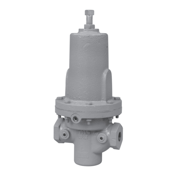
cashco DA5 Руководство по установке, эксплуатации и техническому обслуживанию
Просмотреть онлайн или скачать pdf Руководство по установке, эксплуатации и техническому обслуживанию для Контроллер cashco DA5. cashco DA5 16 страниц. Direct-acting, spring loaded back pressure regulator

ISO Registered Company
I. DESCRIPTION AND SCOPE
The Model DA5 is a spring operated back pressure regulator used to control upstream (inlet or P1) pressure. Sizes
are 1/2" (DN15), 3/4" (DN20), 1" (DN25), 1 1/4" (DN32), 1 1/2" (DN40), 2" (DN50), 2 1/2" (DN65), 3" (DN80) and
4" (DN100). With proper trim uti li za tion, the unit is suitable for liquid, gaseous, or steam service. The Model DA5
is available in a more common "reverse" flow direction arrangement, that is balanced against outlet pressure varia-
tions, and a "standard" flow direction arrangement that is unbalanced. Refer to Technical Bulletin DA5-TB for design
conditions and selection rec om men da tions. (NOTE: This product was formerly iden ti fied as a Model D5 or Type V;
a Model DA5, D5 and Type V are one and the same product.)
II. REFERENCES
Refer to Technical Bulletin DA5-TB and DAG-TB for
tech ni cal specifications of a Model DA5 regulator.
III. INSTALLATION
For welded installations, all internal trim parts, seals and
diaphragm(s) must be removed from reg u la tor body prior
to welding into pipeline. The heat of fusion welding will
dam age non-metallic parts if not re moved. NOTE: This does
not apply to units equipped with extended pipe nip ples.
1. Install per direction of flow arrow indicated on body,
or "IN" and "OUT" markings.
2. Regulator may be rotated around pipe axis 360
degrees. For ease of maintenance, the rec om-
mend ed position is with the spring chamber (4)
upwards. In liquid service it is recommended that
the spring cham ber be oriented down wards, and
that a cus tom er supplied and installed vent valve
be pro vid ed at the external sensing connection
to bleed-off trapped gas/air under the diaphragm
during initial startup.
3. Provide space below, above, and around reg u la tor
for removal of parts during maintenance.
INSTALLATION, OPERATION & MAINTENANCE MANUAL (IOM)
MODEL DA5
DA5 - DIRECT-ACTING, SPRING LOADED
BACK PRESSURE REGULATOR
CAUTION
SECTION I
SECTION II
CCW – Counter Clockwise
CW
ITA
SECTION III
4. Install block valves and pressure gauges to pro-
vide means for adjustment, operation, bypass, or
removal of the regulator. A pipeline strainer is
recommended upstream of inlet port to remove
typical pipe line debris from entering valve and
damaging internal "soft goods", primarily the dy-
namic side seal and V-TFE seat when applied.
5. Upstream Sensing Installation Considerations –
Internal or External Sensing:
a. The regulator may be installed with internal
or external sensing. Unless otherwise spec i-
fied, the regulator is supplied by the factory
with internal sensing. The regulator may be
con vert ed in the field to external sensing. (See
Section VII maintenance, Part H – Converting
Internal/External Sensing.
b. Reference DAG-TB, Table DAG-12 for rec om-
men da tions for applying external pressure
sensing.
c. For internal sensing, no external line is re-
quired. For external sensing, use an external
control line. The line is connected from the
port 1/4" (DN8) NPT on the side of the body
di a phragm flange (see following schematic)
to a pressure tap upstream of the regulator.
ABBREVIATIONS
– Clockwise
– Inner Trim Assembly
IOM-DA5
03/16
