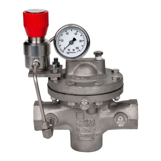
cashco SLR-1 Руководство по установке, эксплуатации и техническому обслуживанию
Просмотреть онлайн или скачать pdf Руководство по установке, эксплуатации и техническому обслуживанию для Контроллер cashco SLR-1. cashco SLR-1 18 страниц. Direct-acting, pressure loaded, pressure reducing regulator with self-relieving loader

ISO Registered Company
I. DESCRIPTION AND SCOPE
The Model SLR-1 uses the pressure set point of a self-relieving loader to control the outlet pressure of the
main reducing regulator. Sizes are 1/2" (DN15), 3/4" (DN20), 1" (DN25), 1-1/4" (DN32), 1-1/2" (DN40), 2" (DN50),
3" (DN80) and 4" (DN100). This model is suitable for gaseous applications.
II. REFERENCES
Refer to Technical Bulletin SLR-1-TB for tech ni cal
specifications for this reg u la tor.
III. INSTALLATION
For welded installations, all internal trim parts, seals
and diaphragm(s) must be removed from reg u la tor
body prior to welding into pipeline. The heat of fusion
welding will dam age non-metallic parts if not re moved.
1. This regulator may be rotated around pipe axis
360 degrees. For ease of maintenance, the
rec om mend ed position is with the cover dome
(25) up wards.
2. Provide space below, above, and around reg u la-
tor for removal of parts during maintenance.
3. Install block valves and pressure gauges to pro-
vide means for adjustment, operation, bypass,
or removal of the regulator. A pipeline strainer
is recommended before inlet to remove typical
pipe line debris from entering valve and damaging
internal "soft goods", primarily the dynamic seal.
4. Downstream Sensing Installation Considerations
– Internal or External Sensing:
a. The regulator may be installed with inter-
nal or external sensing. Unless otherwise
INSTALLATION, OPERATION & MAINTENANCE MANUAL (IOM)
MODEL SLR-1
DIRECT-ACTING, PRESSURE LOADED,
PRESSURE REDUCING REGULATOR
with SELF-RELIEVING LOADER
CAUTION
SECTION I
SECTION II
CW
CCW –
SECTION III
Installation of adequate overpressure pro tec tion is recom-
mended to pro tect the reg u la tor from overpressure and
all down stream equip ment from damage in the event of
regulator failure.
spec i fied, the regulator is supplied by factory
with internal sensing. The regulator may be
con vert ed in the field to external sensing. (See
Section VII Maintenance, Part G – Converting
Internal/External Sensing.
b. Reference SLR-1-TB, Table -11 for rec om-
men da tions when to apply external sensing.
c. For internal sensing, no external line is re-
quired. For external sensing, use an external
control line. The line is connected from the
1/4" (DN8) NPT tap (Port 5 – See Fig. 5) on
the side of the body di a phragm flange to a
pressure tap down stream of the regulator. Use
1/4" or 3/8" (DN8 or 10) outer di am e ter tubing
or 3/8" (DN10) pipe having an inner di am e ter
equiv a lent to Schedule 40 pipe.
ABBREVIATIONS
–
Clockwise
Counter Clockwise
ITA
–
Inner Trim Assembly
CAUTION
IOM-SLR-1
02-20
