Danfoss VLT AutomationDrive FC 301 Руководство по установке - Страница 14

Просмотреть онлайн или скачать pdf Руководство по установке для Приводы постоянного тока Danfoss VLT AutomationDrive FC 301. Danfoss VLT AutomationDrive FC 301 18 страниц. 24 v dc supply
Также для Danfoss VLT AutomationDrive FC 301: Руководство по установке (20 страниц), Руководство по установке (6 страниц), Руководство по установке (8 страниц), Руководство по установке (6 страниц), Руководство по установке (16 страниц), Руководство по установке (16 страниц), Руководство по установке (8 страниц), Руководство по установке (6 страниц)
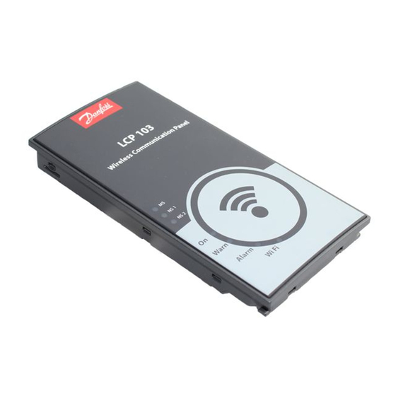
Danfoss VLT AutomationDrive FC 301 Руководство по установке
Installation
Wiring procedure for enclosure types D, E, and F
1.
Mount the pre-configured cable wires with the
connectors on the fieldbus option. For cable
specifications, refer to chapter 3.8.2 Cable Specifi-
cations.
3
3
2.
Fix the cable to the metal base plate using the
springs, see Illustration 3.12.
3.
Tie down the cable and route it with other
control wires inside the unit, see Illustration 3.12.
Illustration 3.12 Wiring for Enclosure Types D, E, and F
NOTICE
Do not strip the Ethernet cable. Do not ground it via the
strain relief plate. Ground the screened Ethernet cables
through the RJ 45 connector on the PROFINET interface.
12
Installation Guide

3.9 Reassembling Cover

3.10 Applying Power

Follow the instructions in the frequency converter
Operating Instructions to commission the frequency
converter. The frequency converter automatically detects
the PROFINET interface and 2 new parameter groups
(group 9 and group 12) appear.

3.11 Checking Network Cabling

NOTICE
After installing the PROFINET interface, be aware of the
following parameter settings:
8-01 Control Site: [2] Control word only or [0] Digital and
control word
8-02 Control Word Source: [3] Option A
Danfoss A/S © Rev. 07/2014 All rights reserved.
1.
Mount the new front cover and the LCP.
2.
Attach the sticker with the correct product name
to the front cover.
MG90U402