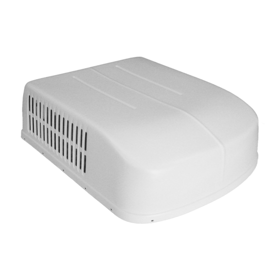
Duo-Therm 57915.631 Руководство по установке - Страница 11
Просмотреть онлайн или скачать pdf Руководство по установке для Кондиционер Duo-Therm 57915.631. Duo-Therm 57915.631 17 страниц. Roof top air conditioner/heat pump
Также для Duo-Therm 57915.631: Руководство по установке и эксплуатации (17 страниц)

A. Position the control box (standing up) with the 6 pin connector to the curb side of the vehicle and the service access facing
the rear of the vehicle. See FIG. 9.
B. CONNECTION OF 115 VOLT AC SUPPLY
1. Route the previously run AC power supply line through the Romex Connector and into relay control junction box. See
FIG. 9.
2. Reach up into the return air opening of the air conditioner/heat pump and pull the wire harness down and fit the six pin
plug into the matching plug on the control box. See FIG. 9.
3. Inside the control box, connect the white to white; black to black; and green to green or bare copper wire using
appropriate sized twist wire connectors. Tape the twist wire connectors to the supply wiring to assure they do not
vibrate off.
4. Tighten screws on Romex connector being careful not to pinch and cut into the insulation on power supply leads.
5. Push excess wires into junction box. Install junction box cover, with model number/serial number facing out onto the
relay control box with #8 x 3/8" blunt point Phillips head screw provided.
Note: Model Number /Serial Number label must face out.
FIG. 9
Center Unit From Below
Connect AC Power
Leads in Control Box
Front Of
Vehicle
Connect 6 Pin
Plug Into Control
Box.
B. CONNECTION OF LOW VOLTAGE WIRES
1. Connect the previously run +12VDC to the red wire labeled +12V protruding from the relay control box (Do not connect
wires if using the 3308120.XXX Genesis Air Filtration System Return Air Kit Return Air Kit).
2. Connect the previously run -12VDC to the black wire labeled - 12V protruding from the relay control box (Do not connect
wires if using the 3308120.XXX Genesis Air Filtration System Return Air Kit).
3. Connect red/white wire to the thermostat +7.5 terminal.
4. Connect the unit/control box green wire to the thermostat "GND" terminal.
5. Connect the unit/control box yellow wire to the thermostat "COOL" Terminal.
6. Connect the unit/control box tan wire to the thermostat "FAN" terminal.
7. Connect the unit/control box blue wire to the thermostat "HI FAN" terminal.
8. Connect the unit/control box orange wire to the thermostat "HS/HP" terminal (if applicable).
9. Connect the unit/control box unit white wire to the thermostat "FUR" terminal (if applicable).
10. Connect the unit/control box blue/white wires to the two furnace control wires (if applicable).
Note: See FIG. 9A for Thermostat connection points.
FIG. 9A
D. Plug unit electrical cord into the mating connector on the relay control box. These connectors are polarized and will easily
snap together. Do not force.
ANALOG DUCTED INSTALLATION INSTRUCTIONS
9. WIRING OF CONTROL SYSTEM
Gasket
!
Disconnect 115 volt AC. Failure to follow
these instructions could create a shock haz-
ard causing death or severe personal injury.
This product is equipped with a 3-wire
(grounded) system for protection against
shock hazard. Make sure that the appliance
is wired into a properly grounded 115 volt AC
circuit and the polarity is correct. Failure to
do so could result in death, personal injury
or damage to the equipment.
11
WARNING
!
WARNING
