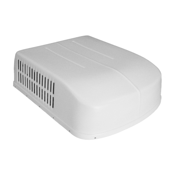
Duo-Therm 600 Series PENGUIN Руководство по установке и эксплуатации - Страница 7
Просмотреть онлайн или скачать pdf Руководство по установке и эксплуатации для Кондиционер Duo-Therm 600 Series PENGUIN. Duo-Therm 600 Series PENGUIN 17 страниц. Roof top air conditioner/heat pump
Также для Duo-Therm 600 Series PENGUIN: Руководство по установке (17 страниц)

5. AIR DISTRIBUTION SYSTEM INSTALLATION
A. Dometic Corporation recommends the basic configuration shown on page 8, for installing this air conditioner system. We have
found by testing , that this configuration works best in most applications of this air conditioner. It is the responsibility of the
Installer of this system to review each RV floor plan and determine the following:
1. Duct size
2. Duct layout
3
Register size
4. Register location
5. Thermostat location
These items must be determined in conjunction with the Air Distribution System and Sizing and Design Requirements listed
in the chart on page 6.
Important:
Alternate configurations and methods may be used which still allow the air conditioner to operate
properly; however, these alternate configurations and methods must be approved by the Dometic Corporation in
writing. The following instructions are based upon the use of Dometic 3105007.XXX Return Air Kits , 3105935.XXX
Quick Cool Kits, or 3308120.XXX Genesis Air Filtration System (3308120.XXX Genesis Air Filtration System
indicator light requires 12VDC power from the vehicle). The 3104998.XXX control kit has the mounting bolts
supplied for use with these kits.
B. ROOF AND CEILING OPENING PREPARATION
1. A 14-1/4" x 14-1/4" (±1/8") opening must be cut through the roof and ceiling of the RV. This opening must be located
between the roof reinforcing members.
2. Mark a 14-1/4" x 14-1/4" (±1/8") square on the roof and carefully cut the opening.
3. Using the roof opening as a guide, cut the matching hole in the ceiling.
4. The opening created must be framed to provide adequate support and prevent air from being drawn from the roof cavity.
Lumber 3/4" or more in thickness must be used. Remember to provide an entrance hole for power supply wiring and
thermostat cable.
5. The 14-1/4" x 14-1/4" (±1/8") opening is part of the return air system of the air conditioner and must be finished in
accordance with NFPA Standard 501C Section 2.7.
6. Route a copper 12 AWG, with ground, 115VAC supply line from the fuse or circuit breaker box to the roof opening.
a. This supply line must be located in the front portion of the
b. The power supply MUST be on a separate Time Delay Fuse or HACR Circuit Breaker (20 amp for 579, 590, 591,59516
and 600 series and 15 amp for 59528, 59529 and 59530).
c. Make sure at least 15" of supply wire extends into the roof opening. This ensures easy connection at the junction
box.
Note: if using the 3308120.XXX return air cover. Route a 18 - 22 AWG. fused 12VDC power supply lead from the
converter or battery to the roof opening. Make sure 15" of wire extends into the opening.
d. Wiring must comply with all National, State and Local Wiring Codes.
e. Use a steel sleeve and a grommet or equivalent methods to protect the wire where it passes into the opening.
7. See Section 6. Thermostat & Cable Installation
WARNING
!
There may be electrical wiring between the
roof and the ceiling. Disconnect 115 volt AC
power cord and the positive (+) 12 volt DC
terminal at the supply battery. Failure to fol-
low this instruction may create a shock haz-
ard causing death or severe personal injury.
INSTALLATION INSTRUCTIONS DUCTED BI-METAL
14-1/4" x 14-1/4" (±1/8")
7
opening.
