Duomo SGM595 Руководство - Страница 3
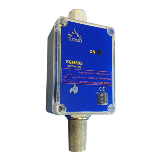
Просмотреть онлайн или скачать pdf Руководство для Детекторы газа Duomo SGM595. Duomo SGM595 8 страниц. Natural gas / propane sensor

Connections and LED indicator
Important Notes
IMPORTANT: Assembly / maintenance of the appliance must be carried out by qualified personnel and in
accordance with applicable laws and regulations.
The manufacturer assumes no responsibility for the use of products that have to comply with particular
environmental and / or installation standards.
IMPORTANT: Before connecting the equipment, it is recommended that you read the instruction manual
carefully and keep it for future reference.
Electrical Connections
IMPORTANT:
instructions and the connections according to Regulations in force, keeping in mind that the signal cables should
be laid separate from the power cables.
3
2
1
t: 01905 797989
e: [email protected] | w: www.duomo.co.uk
Before connecting to the mains power, ensure the voltage is correct. Carefully follow the
CONNECTING TERMINAL
1. Positive Suplly Voltage
2. 0V
3. Return Sensor Voltage
POWER ON LED
Connecting Terminal
This LED illuminates Green when power is ON and the sensor has a power
supply from the controller.
Power ON LED
Diagnostic port
Flashing red indicates gas is being detected.
Constant red indicates alarm state.
Constant Amber indicates fault condition.
DIAGNOSTIC PORT
This can be connected to a A hand-held datalogger that can printout
information about the sensor (serial number, powering up information,
sensor condition, alarm activations, expected lifespan, auto adjusts made
and the preset calibration state.
Tuning the Sensor to the Installation
Upon completion of the install measure the DC voltage between terminals 2
and 3 in the sensor plug. This is located at the top right hand corner of the
SGM595 printed circuit board. If the reading is not between 0.8 - 0.9vDC you
will need to trim JP1.
JP1 is located on the PCB to the left of the PCB lower securing screw. Using
a wire link briefly short the two terminals of JP1 until the power green LED
flashes. When the power green LED flashes remove the link. Once the LED has
stopped flashing recheck the voltage between terminals 2 and 3 on the sensor
plug. If the voltage is still outside 0.8-0.9vDC conduct the procedure again.
3
