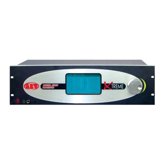
AEV Xtreme II Руководство - Страница 6
Просмотреть онлайн или скачать pdf Руководство для Компьютерное оборудование AEV Xtreme II. AEV Xtreme II 19 страниц. Digital broadcast audio processor
Также для AEV Xtreme II: Руководство (19 страниц)

AEV Xtreme II Digital Audio Processor
Sec. 1-4-1 Analogue inputs/outputs
The analogue inputs are installed on two XLR female connectors, located on the rear panel. The input is ≥10
KΩ high impedance, and the inputs accept signals up to +12dBu. The analogue outputs are provided with two
XLR male connectors, located on the rear panel. The outputs can pilot loads of ≥10 KΩ.
Sec. 1-4-2 Digital inputs/outputs
The digital input is provided with an XLR female connector, located on the rear panel. Balanced input with a 110Ω
impedance. The digital output is provided with an XLR male connector, located on the rear panel. Impedance, as
for the input, is 110 Ω.
Sec. 1-4-3 MPX outputs
The stereo coder (optional) has two outputs on a non-balanced BNC connector, located on the rear panel. Each
outputcan be connected via a cable with maximum length of 3 mt, before any signal deterioration occurs.
The levels of the outputsare controlled by the "Jog" on the front panel.
Sec. 1-4-4 RDS input (optional)
The RDS input is active in the FM version, if the RDS internal coder is not installed. It is provided with a BNC
connector, located on the rear panel, with 10 KΩ impedance.
Accepted levels range between 0 and -14dB.
Sec. 1-4-5 SCA input
A non-balanced BNC connector, for use with the SCA signal, is also available on the input. It can accept any type
≥ of 23 KHz subcarrier. The subcarrier is mixed with MPX signals. Accepted levels range between 0 and -14dB.
Sec. 1-4-6 RDS output (optional)
The RDS coder (optional) has an output on a non-balanced BNC connector, located on the rear panel. The output
level is fixed at 0dBu. It is also present on the MPX+RDS output with a level which can be adjusted from - infinite
to -17.5dB.
Sec. 2 Positioning and initial preset of Xtreme II
Sec. 2-1 Xtreme's best position
Xtreme II's best position is as close as possible to the transmitter, so that the stereo encoder output can be
connected to the transmitter via a route causing minimal variation to the wave shape of the MPX signal.
Xtreme II outputs can pilot a coder with cable length of up to 3 m before any appreciable degradation of the MPX
signal is noted.
If this is impossible, the best solution is either to: power up an external coder located close to the transmitter
energiser via Xtreme's base band analogue output, or to use the digital output with an essentially flat frequency
response plus a constant wave train delay in the range 30 Hz to 15 KHz.
To ensure maximum transmission quality, all appliances downstream of the studio must be carefully aligned and
must satisfy the appropriate standards for wave width, distortion, wave train delay and gain stability.
These appliances must be re-checked at reasonable intervals.
It is therefore important that the sound source connected to Xtreme II has low noise at output, the flattest
possible requency response and low distortion.
Sec. 2-2 At first power-up
Before powering up Xtreme II, make sure that mains power matches the value shown on the rear of the power
supply and hat the electric system to which Xtreme II is connected, is supplied with a good grounding system.
AEV Broadcast Srl – via della Tecnica 33 – 40050 Argelato (BO) Italy
Web site www.aev.eu
e-mail [email protected]
6
