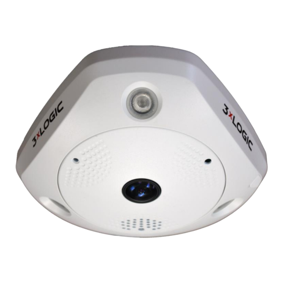
3xLogic VISIX 360 Руководство по установке оборудования - Страница 10
Просмотреть онлайн или скачать pdf Руководство по установке оборудования для Камера безопасности 3xLogic VISIX 360. 3xLogic VISIX 360 16 страниц. 3xlogic visix 360 network camera
Также для 3xLogic VISIX 360: Руководство по установке (16 страниц)
2 Installation
Before you start:
Make sure the device in the package is in good condition and all the assembly parts are included.
Make sure all the related equipment is power-off during the installation.
Check the specification of the products for the installation environment.
Make sure the power supply is matched with your required voltage to avoid damage.
If the product does not function properly, please contact your dealer or the nearest service center. Do not
disassemble the camera for repair or maintenance by yourself.
Make sure that the wall is strong enough to withstand three times the weight of the camera.
For the camera that supports IR, you are required to pay attention to the following precautions to prevent IR
reflection:
Dust or grease on the dome cover will cause IR reflection. Please do not remove the dome cover film until
the installation is finished. If there is dust or grease on the dome cover, clean the dome cover with clean
soft cloth and isopropyl alcohol.
Make sure that there is no reflective surface too close to the camera lens. The IR light from the camera
may reflect back into the lens causing reflection.
The foam ring around the lens must be seated flush against the inner surface of the bubble to isolate the
lens from the IR LEDS. Fasten the dome cover to camera body so that the foam ring and the dome cover
are attached seamlessly.
2.1 Ceiling Mounting
Steps:
1. Drill three screw holes and the cable hole according to the supplied drill template.
10225 Westmoor Drive, Suite 300, Westminster, CO 80021 | www.3xlogic.com | (877) 3XLOGIC
Hardware Install Manual | VISIX 360 Network Camera
A
1
TOP
Drill Template
HoleA: for cables routed through the ceiling
Screw hole 1: for Mounting Base
1
Figure 2-1 Drill Template
1
10