Dantel B11-48001-01 Руководство по установке и эксплуатации - Страница 5
Просмотреть онлайн или скачать pdf Руководство по установке и эксплуатации для Блок управления Dantel B11-48001-01. Dantel B11-48001-01 12 страниц. Fuse module

CIRCUIT DESCRIPTION
JP1
-B
AND
ATTERY
48001-1097 <90-00033>
Two sets of Form-C contacts activate external alarm circuits
when the relay is not active. Two external alarm inputs at pins
52 & 56 allow the alarm circuit to be operated by an external
contact to negative battery.
E
XTERNAL
Edge connector pin 28 is available for providing power to exter-
nal equipment. -Battery supplied to pin 31, 32, 35, or 36 is
routed directly to pin 28, bypassing any fuses.
INSTALLATION
T
he actual installation of this module is simple. To install the
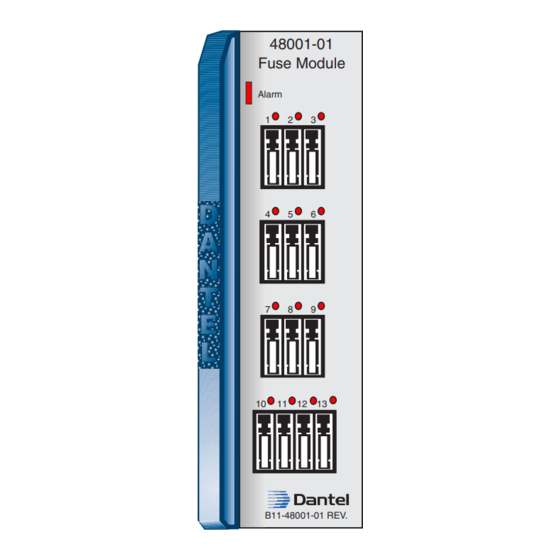
B11-48001-01 Fuse Module, place it in the proper slot in the
equipment shelf. However, several factors deserve attention
before installation:
I
NPUTS
Refer to Fig. 2. The module is equipped with a jumper (JP1).
This jumper selects one of the following modes of operation:
♦
♦
♦
Refer to Table A, in the Circuit Description section.
JP1 strapped 1 & 2
♦
♦
F
F
USE
EED
Single input.
Redundant inputs.
Two independant inputs.
Single Input
Connect one power supply to pins 35 and/or 36 or 31 and/or
32. That one power supply powers both fuse groups.
Redundant Inputs
Connect one power supply to pins 35 and/or 36. Connect a
second power supply to pins 31 and/or 32. Both supplies pro-
vide power to both fuse groups.
P
5
AGE
