AudioStak ProSwitch PRSW-4HL-PCB Руководство и инструкция по установке - Страница 4
Просмотреть онлайн или скачать pdf Руководство и инструкция по установке для Блок управления AudioStak ProSwitch PRSW-4HL-PCB. AudioStak ProSwitch PRSW-4HL-PCB 20 страниц.

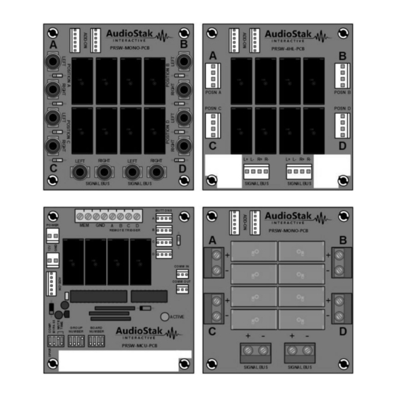
Main Module PRSW-MCU-PCB
Module Power Connectors
ADD-ON Connector
DIP Switches
Figure 1: Main Module PRSW-MCU-PCB
Main Module PRSW-MCU-PCB (Figure 1) is used to read push-buttons and communicate with other modules in
the system. Each set of four components or speakers requires one Main Module. It controls and synchronizes
ADD-ON modules to switch signals. DIP switches are used to set the Module's address and other functions.
Remote turn-on power can be supplied using the Component Remote Turn-on Power Connectors (5A MAX).
This allows only active components to be turned on to save power and allow a smaller system power supply.
This is the method recommended by AudioStak.
The Active LED indicates when the module has an active position or flashes in different modes as a
troubleshooting aid in the event of a wiring error or module failure.
Overview – ProSwitch Modules
Component Power Connector
POWER
MEM
GND
GROUP
BOARD
NUMBER
NUMBER
Writing/Labelling Area
Button Connectors
BUTTONS
A
A
B
C
D
B
REMOTE TRIGGER
C
D
PRSW-MCU-PCB
Mounting Standoffs
COMM IN
COMM Bus Connectors
COMM OUT
Active LED
ACTIVE
