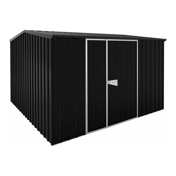
Duratuf Gurdian Sheds GG101 Инструкция по сборке Руководство - Страница 14
Просмотреть онлайн или скачать pdf Инструкция по сборке Руководство для Хранение на открытом воздухе Duratuf Gurdian Sheds GG101. Duratuf Gurdian Sheds GG101 16 страниц.

ROOF ASSEMBLY CONT...
STEP 3:
• Position 1 x roof sheet so that the top of the
sheet is at the centre of the Ridge Beam
and the side of the sheet over hangs the end of the Ridge
Beam and the Top Plate by 15mm.
• Ensure the Ridge Beam and the Top Plate are straight.
• Nail /screw 4 x corners of the Roof Sheet as shown, ensuring
the ribs on the Roof Sheet line up with the front Roof Sheet
and the back Wall Sheet. Fasten off the first sheet.
STEP 4:
• Position the second Roof Sheet, and rivet to first roof sheet as
shown.
• Fasten off as per Step 2.
• Rivet and nail/screw off the remaining Roof Sheets, ensuring
the ribs line up with the front Roof Sheets and the back Wall
Sheets.
STEP 5:
• Place barge flashings on roof at end of shed
ensuring the diagonal trimmed end is facing
out. (See diagram on pg 5)
• Rivet the Barge Flashings to the roof and the
side wall, using four rivets on top of barge
and four into the side (fig.3).
STEP 6:
• Rivet the 2 Ridge Caps together using 4
rivets, so total flashing is 3.220m long. Rivet
the Ridge Cap to the centre of the roof us-
ing 12 x rivets as shown (fig.2).
STEP 7:
• Place spouting in position and rivet to Barge Flashings
at each end and rivet to roof sheets (1 rivet per 1
sheet) (fig.4).
IMPORTANT
Use 50mm Clouts only on ribs covered by flashings, shown in fig.2.
Predrill holes using a 3.5mm drill bit.
Use Roofing Screws on all other ribs and pans. Ensuring screws are not
overtightened as this can damage the seal and cause the shed to leak.
BACK WALL
RIDGE
SIDE
WALL
Barge
X 4
fig.3
13
TOP PLATE
BACK WALL
BOTTOM PLATE
SIDE
WALL
TOP PLATE
BACK WALL
BOTTOM PLATE
SIDE
WALL
= Clout
= Screw
TOP PLATE
BOTTOM PLATE
FRONT
WALL
X 4
Spouting
SIDE
FRONT WALL
SIDE
FRONT WALL
fig.1
SIDE
WALL
fig.4
