APLICOM A1 Руководство по установке - Страница 4
Просмотреть онлайн или скачать pdf Руководство по установке для GPS APLICOM A1. APLICOM A1 8 страниц.

Electrical Installation
Read warnings chapter on page 5 on this document.
•
Protect power supply lines (6,8...32Vdc) with 3A (max 10A) fuse at power supply end of line.
•
Connect the cables to A1 device and peripherals as advised in the connection guide. Figure 11. IGN- line
•
must be always connected.
Install the GSM/GPRS antenna and cables as far away as possible (minimum 1 metres recommended)
•
from the radio antenna or other electrical devices to avoid any interference.
Additional information: Application note K505002 Cabling of Aplicom Products.
Avoid ground loops! It is highly recommended to connect all A1 and peripherals ground connections to a
•
single point. It is also recommended to use non-grounding antennas.
Insert the SIM card to the SIM card slot. Figure 12.
•
Insert optional Internal battery. Figure 12.
•
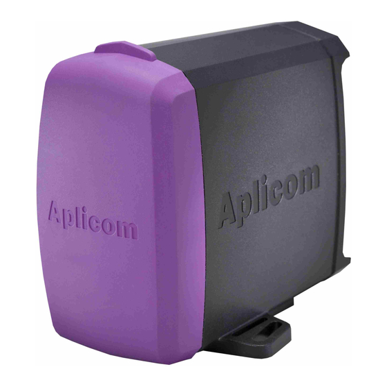
Attach the elastic protective cover. Figure 1.
•
A1 device versions with CAN bus functionality ** do not include internal bus terminator resistor (120 ).
•
The led beside the battery connector indicates the battery charging state. When lit:
•
-
Green, battery is fully charged
-
Yellow, charging is in progress
-
Red, indicates an error condition e.g. battery overheating
Disconnecting ground lines shall not be done while unit is connected to power supply of the vehicle. This
•
will cause voltage leak between IO connections causing possible problems in external devices connected
to them.
When digital tachograph is connected to A1 they must share a common ground potential. If the ground
•
potential is not common, the serial connection between units may not work. Use the ground wire of the
provided cable to secure the ground potential.
Figure 5.
PWR
Pin 1, Power in
Pin 2, Ignition
Pin 3, +12V, Ext. Battery *
Pin 4, GND
IO 1
Pin 1, PWROUT ***
Pin 2, OC1/DOUT1
Pin 3, DIN5/PLS_CNT1
Pin 4, DIN1/AD1
Pin 5, DIN2/AD2
Pin 6, GND
BUS 1
Pin 1, NC
Pin 2, LED_CTRL
Pin 3, 1-WIRE
Pin 4, GND
IO 2
Pin 1, PWROUT ***
Pin 2, OC2/DOUT2
Pin 3, DIN6/PLS_CNT2
Pin 4, DIN3/AD3
Pin 5, DIN4/AD4
Pin 6, GND
Figure 6.
BUS 2
Pin 1, K-LINE
Pin 2, CAN_H **
Pin 3, CAN_L**
Pin 4, RS485-A
Pin 5, RS485-B
Pin 6, GND
Figure 7.
Figure 8.
3
