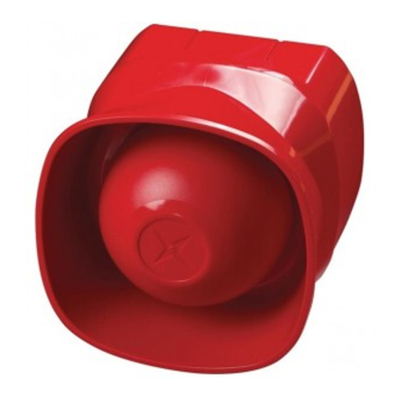
Apollo 55000-298 Руководство по установке
Просмотреть онлайн или скачать pdf Руководство по установке для Система безопасности Apollo 55000-298. Apollo 55000-298 2 страницы. Multi-tone open-area alarm devices
Также для Apollo 55000-298: Руководство по установке (2 страниц)

Group Address Setting
In group mode the Multi-tone Open-area Alarm Devices responds to an additional address referred to
as the group address, which is used to activate groups of sounders simultaneously. Individual units con-
tinue to respond to their own addresses and report their status in the normal way. A group address is set
on a four-segment DIL switch which is factory set to 0000. A group address may be any spare address
within–and only within–the range 112 to 126 inclusive. The required group address is set in accordance
with the following table.
DIL switch
DIL switch
setting
setting
addr
1234
addr
1234
addr
112
1111
117
0101
122
113
0111
118
1001
123
114
1011
119
0001
124
115
0011
120
1110
125
116
1101
121
0110
126
Note: group mode is disabled if the group address DIL switch is set to 0000, irrespective of the protocol
message.
Commissioning
It is important that the Multi-tone Open-area Alarm Devices be fully tested after installation. An XP95
Test Set, part no. 55000-870, may be used to carry out func tion al testing of individual units. The test set
can also perform data integrity tests of an entire system.
Troubleshooting
Before investigating individual units for faults, it is important to check the system wiring is fault-free. Earth
faults on data loops may cause communication errors.
Fault Finding
Problem
Possible Cause
No response or missing
Incorrect address setting
Incorrect loop wiring (polarity reversed)
Too many Sounders with Visual Indicator between isolators
Analogue value 2
Visual Indicator failed (Sounder with Visual Indicator version only)
Analogue value 4
Incorrect group or individual address setting
Device fault
Incorrect group address setting
Device fails to operate
Control panel has incorrect cause and effect programming
Incorrect group address setting
Locking Mechanism
To meet the requirements of EN54 Part 3 and the Construction Products Directive, the devices have
been designed to lock to its base. To release the Type A device from its base, a release key (supplied)
must be used to release the latch in the side of the base. To unlock the Type B (Weatherproof) versions,
a hex driver (supplied) is required.
©Apollo Fire Detectors Ltd 2003–2018
Apollo Fire Detectors Ltd, 36 Brookside Road, Havant, Hants, PO9 1JR, UK
Tel +44 (0)23 9249 2412 Fax +44 (0)23 9249 2754
Email: techsales@apollo- re.co.uk Website: www.apollo- re.co.uk
PP2248/Issue 11
DIL switch
setting
1234
1010
0010
1100
0100
1000
Multi-tone Open-area Alarm Devices
Installation Guide
General
This guide describes the installation of the following products:
Part No
Product Name
55000-278
Multi-tone Open-area Sounder
55000-279
Multi-tone Open-area Sounder
55000-274
Multi-tone Weatherproof Open-area Sounder
55000-275
Multi-tone Weatherproof Open-area Sounder
55000-293
Multi-tone Open-area Sounder with Visual Indicator and Isolator*
55000-294
Multi-tone Open-area Sounder with Visual Indicator and Isolator*
55000-291
Multi-tone Open-area Sounder with Visual Indicator*
55000-292
Multi-tone Open-area Sounder with Visual Indicator*
Multi-tone Weatherproof Open-area Sounder with Visual Indicator
55000-298
and Isolator*
Multi-tone Weatherproof Open-area Sounder with Visual Indicator
55000-299
and Isolator*
55000-296
Multi-tone Weatherproof Open-area Sounder with Visual Indicator *
55000-297
Multi-tone Weatherproof Open-area Sounder with Visual Indicator *
* This is a supplementary indicator and is not to be used where a VAD is speci ed. This product in not
EN54-23 compliant.
The Multi-tone Open-area Alarm Devices are connected to control panels which use the
Discovery or XP95 protocol. It complies with the requirements of EN54–3: 2001. Versions with isolator also
comply with EN54–17: 2005.
Tones incorporated in the product are:
Apollo Standard Tone, Slow Whoop Tone to NEN2575 and DIN 33404 Tone. There are 2 volume settings in
each variant.
The versions which incorporate a short-circuit isolator have a yellow indicator LED, which illuminates
through the lens if a short circuit is detected on the loop wiring.
Mounting the Backbox
The backbox is removed by using either an unlocking key (Type A versions) to press in one of the retain-
ing lugs, or a hex driver (Type B versions).
The Type A product has 6 slotted knockouts on the backbox and is installed directly to the mounting
surface. For the Type B product, t the backbox to the mounting surface with four screws using the holes
in each corner (see Fig 1). Do not drill through the backbox.
To ensure that there is a good seal between the back box and the unit, the mounting surface should be
as at as possible and the mounting screws not over tightened.
Wiring Details
Note: This product is polarity sensitive (supply reversal protected) and will not function if wired incor-
rectly.
Drill holes for cable entry as appropriate for the installation. Drill guides are marked on the backbox. To
maintain the integrity of the Type B product it is essential that suitable cable glands be used.
Connect the loop cables to the terminal block, observing polarity and functional earth/screen if appli-
cable. The wiring terminals accept solid or stranded cables up to 2.5mm².
The maximum number of Multi-tone Open-area Alarm Devices permitted between standard XP95
isolators (part no. 55000-720) or isolating bases (part no. 45681-321/284) is 20, depending on the loop
loading. Apollo's Loop Calculator is a program available as a free download from www.apollo- re.
co.uk and can be used to check the loading of any proposed loop design.
Type
Colour
Indoor (Type A)
Red
Indoor (Type A)
White
Outdoor (Type B)
Red
Outdoor (Type B)
White
Indoor (Type A)
Red
Indoor (Type A)
White
Indoor (Type A)
Red
Indoor (Type A)
White
Outdoor (Type B)
Red
Outdoor (Type B)
White
Outdoor (Type B)
Red
Outdoor (Type B)
White
