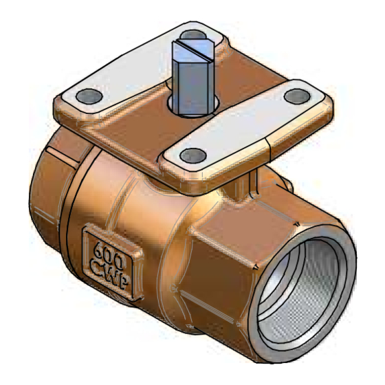
Apollo Valves 77D00501V Руководство - Страница 2
Просмотреть онлайн или скачать pdf Руководство для Блок управления Apollo Valves 77D00501V. Apollo Valves 77D00501V 2 страницы.

INSTALLATION
The Apollo 77D Series Ball valves are bi-directional. They may be installed in vertical or
horizontal pipe runs without regard to flow direction and without regard to stem
orientation.
Note: Valves must be installed in piping systems that comply with the applicable
portions of the ASME B31 standards. Special considerations must be taken with
respect to pipe line expansions and contractions and the media expansion and
contractions within the piping system.
Threaded Connections
Pipe connections to be threaded into these valves should be accurately threaded, clean
and free of foreign material or metal shavings. PTFE pipe tape is recommended for
use as the pipe joint sealant. Two wrenches must be used when making up pipe joints
to these valves. Apply one wrench on the valve end closest to the pipe joint being
tightened and the other wrench to the pipe to prevent transmitting torque through the
valve body joint. Typical pipe make-up is 1-1/2 turns after installing the pipe hand-tight.
Ball valves are intended to be on-off devices operating through 90° rotation of the stem.
This is easily accomplished by using "Apollo" actuators and accessories.
MAINTENANCE
A maintenance history log should be maintained for each valve in the piping system. If
leakage is detected, it should be noted and stopped as soon as possible. Stem seal
and/or seat leakage may be the result of damaged sealing surfaces. Damage may be
the result of changes in service conditions or normal wear. If leakage is noted, the
valve should be de-pressurized, disassembled, and inspected for damage.
Major Overhaul
This type of valve is not normally re-built, but rather replaced. However, where
execution of a major repair is preferred, the following guidelines should be adhered to:
Repair Kits
Before work begins, contact your distributor to acquire appropriate seal repair kit(s).
These kits typically contain a complete set of seats and seals.
Valve
Kit Number
Size
(EPDM)
½"
77D00301E
¾"
77D00401E
1"
77D00501E
1-1/4"
77D00601E
1-1/2"
77D00701E
2"
77D00801E
OPERATION
Kit Number
Kit Number
(FKM)
(Nitrile)
77D00301V
77D00301B
77D00401V
77D00401B
77D00501V
77D00501B
77D00601V
77D00601B
77D00701V
77D00701B
77D00801V
77D00801B
Page 2
Warning: (Required by California) This product contains a chemical known to the state
of California to cause Cancer and Birth Defects or other Reproductive Harm.
Disassembly
1)
After de-pressurizing the system, operate the valve fully open to fully closed to
assure there are no trapped fluids or pressure in the body cavity. Leave the
valve in the closed position.
2)
Remove the actuating mechanism per the manufacture's instructions. Set
aside for reuse.
3)
Remove the valve from the piping system and install pipe plugs in the body
and retainer ports of NPT valves. This will prevent collapsing those areas
during disassembly.
4)
Secure the valve body to a heavy work table in preparation for retainer
removal. It may be necessary to heat the body and retainer joint above 450°F
to breakdown the sealant used to secure the valve halves. Remove the
retainer by turning counter-clockwise using a large pipe wrench.
5)
Remove the ball from the body cavity and inspect. If it is scarred, it is
recommended that the whole valve be replaced. Replacement balls are
available. Used seats should be discarded.
6)
After removal of the ball and seats, press the stem downward into the body to
facilitate removal of the stem bearing and o-rings. Do not damage o-ring
sealing surfaces when removing o-rings and bearing.
7)
Inspect the body and retainer for damage. If heavy scratches or pitting are
found on sealing surfaces, scrap the valve. Replacements for these
components are not offered.
Re-Assembly
1)
Begin the re-assembly process by cleaning each of the component parts with
a clean towel or cloth. If the application permits apply a suitable light lubricant
to the o-rings and seats.
2)
Place the new bearing and o-rings on the stem. Take care not to damage the
o-rings or sealing surfaces during installation.
3)
Carefully insert the stem into the valve body stem bore. Place the flow
indicating mark on top of the stem perpendicular to the centerline of the body
in preparation for ball and seat installation.
4)
Insert the body end seat and ball.
5)
Apply an adequate amount of thread locking compound (Loctite® 609, 648 or
680) to the retainer threads so that it covers no less than two complete
threads opposite of the retainer shoulder.
6)
With the ball in the closed position, thread the retainer into the body and apply
the torque value shown in the table below.
Valve Size
½"
¾"
1"
1-1/4"
1-1/2"
2"
7)
After allowing appropriate set-up time for the thread locking compound, cycle
the valve from open to closed several times to verify free operation.
8)
Re-install the actuator using the manufacture's instructions.
Retainer Torque
(ft-lbs)
25
50
100
200
300
600
Page 3
