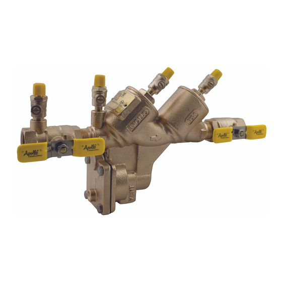
Apollo Valves RP4A Руководство по установке, эксплуатации и техническому обслуживанию - Страница 3
Просмотреть онлайн или скачать pdf Руководство по установке, эксплуатации и техническому обслуживанию для Блок управления Apollo Valves RP4A. Apollo Valves RP4A 16 страниц. Reduced pressure principle (rp) backflow preventer

REDUCED PRESSURE PRINCIPLE BACKFLOW PREVENTER 1/2" 2"
I. DESCRIPTION AND OPERATION
The Reduced Pressure Principle (RP) device consists of two independently-acting, spring-loaded check valves, together with a
hydraulically dependent, mechanically independent pressure di erential relief valve, located in the zone between the check
valves. Two resilient seated shut-o valves and four test cocks complete the assembly.
The rst check is designed to maintain a minimum of 5 psi across the check valve. The second check is designed to maintain a
minimum of 1 psi across the check valve during normal operation. The relief valve operates on a di erential pressure. Supply
pressure on the upstream side of the rst check valve acts against the diaphragm to close the relief valve during normal operation.
In the event of back-pressure, the relief valve will open to maintain the pressure in the "zone" at least 2 psi less than the inlet
pressure. The owing and no ow conditions are illustrated in Figures 1 and 2. A minimum supply pressure of 20 psig is normally
required to fully shut the relief valve and open both checks.
II. INSTALLATION
A. The RP must be installed in an accessible location to facilitate periodic eld testing and maintenance.
B.
The location selected should have adequate drainage for relief valve discharge. The device should never be placed where it
may be submerged in standing water.
C. Flush all upstream piping thoroughly to remove foreign matter prior to installing the device.
D. The device must be installed in the horizontal position. A clearance between the lower most portion of the device and
ood grade or oor should be provided for ease of maintenance.
E.
When shut-o valves are provided separately, they should be installed with a test cock on the upstream side of the inlet shut-
o valve.
F.
After installing the assembly and with downstream or #2 shut-o valve closed, pressurize the device and bleed ALL air
through test cock #4. Then open #2 shut-o valve.
Customer Service (704) 841-6000
www.apollovalves.com
BFMM RP4A SBF
3
