Dataforth SCM9B-D192 Series Руководство пользователя - Страница 5
Просмотреть онлайн или скачать pdf Руководство пользователя для Ретранслятор Dataforth SCM9B-D192 Series. Dataforth SCM9B-D192 Series 7 страниц.

5 SCM9B-D192 USERS MANUAL
An RS-485 repeater is necessary to extend the length of an RS-485
network, or connect more than 32 RS-485 devices on an RS-485
network.
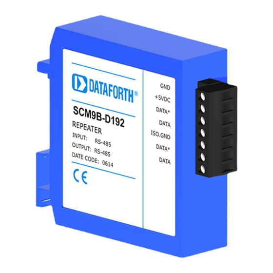
The SCM9B-D192 repeater contains a seven-pin screw terminal plug.
The pin designations are located on the label of each module. The screw
terminals will accept up to #14 gauge wire (AWG). This connector is used
for +5.0Vdc regulated power supply input and both pairs of RS-485 data
lines. The isolated RS-485 input data lines are clearly marked and their
ground reference is isolated by up to 500VRMS from the power supply
ground. The isolated RS-485 input data lines should be attached to the
end of an existing RS-485 network. The serial data received on the
isolated RS-485 input data lines will be re-amplified and retransmitted on
the RS-485 OUT data lines.
.
Figure 1 Connections for SCM9B-D192.
BAUD RATE
The SCM9B-D192 contains a 10-position DIP switch located on the
bottom of each unit. The DIP switch is used to select the correct
communications baud rate and must be set to the same value as the
devices connected to the RS-485 data lines. Each position on the DIP
switch is labeled from 1 to 10. Switch position 1 selects 300 baud. Switch
positions 2 thru 9 select standard baud rates from 600 to 57.6K
respectively. Switch position10 selects 115.2K baud rate. Only one baud
rate switch may be turned on (up position) at one time for proper
operation.
RS-485 TERMINATIONS
The proper termination techniques for any RS-485 system require two
biasing resistors and two termination resistors. The 1kΩ biasing resistors
are connected from the DATA line to +5Vdc and from the DATA* line to
RS-485
Output
RS-485
Input
