DUSKWORK VCO V2 Руководство по сборке - Страница 4
Просмотреть онлайн или скачать pdf Руководство по сборке для Блок управления DUSKWORK VCO V2. DUSKWORK VCO V2 7 страниц.

| DUSKWORK.NET | Self-Tuning VCO V2 Build Guide
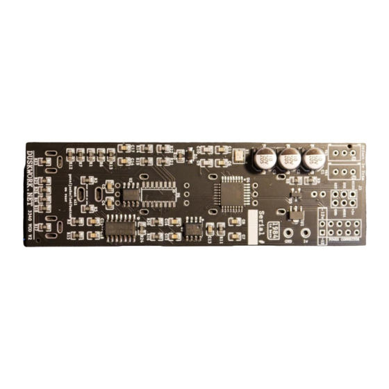
Step 5: Solder in the 2x3 header which will be used to program the board.
Step 6: Solder in the 2x5 header which will be used to supply power to the module.
Step 7: Now it's time to install the 3 main pots which will be used for the wave-mixer. These
should 'click' into place when inserting them onto the PCB.
Don't solder these in yet though! We need to put the other parts loosely in place before so
that the panel all lines up nicely.
Step 8: Now you can put in the 2 x 3.5mm sockets. These (along with the potentiometers)
need to be flush against the PCB, but the LED & button will need to stand proud so they're
the same height. Once you've put all the parts in to line up, put the faceplate on & screw on
the nuts for the button and sockets. You can then solder up those parts once you're happy
with where they're sitting – see photo below for how they should sit:
4
