elsner elektronik 20553 Технические характеристики и инструкции по установке - Страница 2
Просмотреть онлайн или скачать pdf Технические характеристики и инструкции по установке для Аксессуары elsner elektronik 20553. elsner elektronik 20553 2 страницы. Indoor sensor

2.2. Construction of the sensor
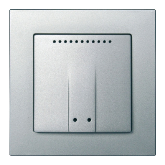
2.2.1. Housing
1
2
2.2.2. Rear view of the baseplate (circuit board) with connection
3
4
Fig. 2
1 Catches
2 Terminal power supply 11...30 V DC
(+/-), Connection polarity independent
3 CO
socket - sensor unit
2
2.3. Sensor assembly
1. First, place the windproof box with the supply connection. Seal the inlet tubes as
well, in order to prevent drafts.
2. Connect the CO
sensor to the sensor circuit board.
2
3. Connect the power supply.
4. Place the CO
sensor unit into the box. The side with the
2
sensor membrane must face the front (Fig. 3)
5. Then screw the baseplate (circuit board) on to the box. The lettering OBEN/TOP
must be at the top and at the front.
6. Position the frame of the switch series and firmly put the sensor housing with the
latches onto the baseplate (circuit board) so that this is fixed to the frame.
2.4. Notes on mounting and commissioning
Never expose the device to water (e.g. rain) or dust. This can damage the electro-
nics. You must not exceed a relative humidity of 95%. Avoid condensation.
2.5. Establish wireless connection
1. Set the control system to teaching (follow the chapter Teaching wireless connec-
tion in the manual).
2. Press the programming button on the WG AQS/TH-UP sensor
The programming button is behind the lower
housing opening on the right.
Use, for example, a paper-clip or a piece of wire to
press the button
3. Observe the response from the control system ("device taught").
WG AQS/TH-UP sensor • Version: 19.12.2018 • Technical changes and errors excepted. • Elsner Elektronik GmbH • Sohlengrund 16 • 75395 Ostelsheim • Germany • www.elsner-elektronik.de • Technical Service: +49 (0) 7033 / 30945-250
Fig. 1
3
1 Baseplate (circuit board)
2 Catches
3 Openings for air circulation
4 Programming LED (recessed)
5 Programming button (recessed) for
4
teaching the device
6 Openings for air circulation
5
(LOWER)
6
1
2
b
5
4 CO
plug - sensor unit
2
5 CO
sensor unit
2
Cable length approx. 110 mm
a Hole distance approx. 43 mm
b Membrane diameter approx. 18 mm
Fig. 3
WG AQS/TH-UP sensor
a
2
