COOK APB Руководство по установке, эксплуатации и техническому обслуживанию - Страница 7
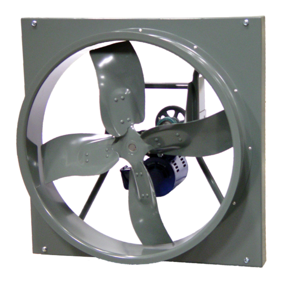
Просмотреть онлайн или скачать pdf Руководство по установке, эксплуатации и техническому обслуживанию для Вентилятор COOK APB. COOK APB 17 страниц. Propeller wall fan

inner ring face with a soft driver may be required. Do
not hammer on the housing.
9.
The outer ring of the bearing is spherical and
swivels in the housing to compensate for
misalignment. Slightly tighten the hold down bolts.
10. Align the setscrews on the bearings and tighten one
setscrew on each bearing.
11. Rotate the shaft to allow the bearing outer rings to
find the center of free movement.
12. Install the propeller on the shaft and adjust the
bearing position to center the propeller in the
opening.
13. Tighten the hold-down bolts to the proper torque.
Refer to the Torque Chart, page 4.
14. Turn the shaft by hand. Resistance should be the
same as it was before the hold-down bolts were fully
tightened.
15. Tighten the bearing setscrews to the specified
torque.
16. Install the pulley and adjust the belt tension.
17. After 24 hours of continuous operation, tighten the
setscrews to the appropriate torque. This assures
the full locking of the inner race to the shaft. Ensure
the socket key or driver is in good condition with no
rounded corners. The key should be fully engaged
in the setscrew and held squarely to prevent the
rounding out of the setscrew socket when applying
maximum torque.
18. Tighten the bearing setscrews to the specified
torque.
19. Install the pulley and adjust the belt tension.
20. After 24 hours of continuous operation, tighten the
setscrews to the appropriate torque. This assures
the full locking of the inner race to the shaft. Ensure
the socket key or driver is in good condition with no
rounded corners. The key should be fully engaged
in the setscrew and held squarely to prevent the
rounding out of the setscrew socket when applying
maximum torque.
Troubleshooting
Problem and Potential Cause
Low Capacity or Pressure
• Incorrect direction of rotation. Make sure the fan
rotates in same direction as the arrows on the motor
or belt drive assembly.
• Poor fan inlet conditions. There should be a straight
clear duct at the inlet.
• Improper propeller alignment.
Excessive Vibration and Noise
• Damaged or unbalanced propeller.
• Belts too loose; worn or oily belts.
• Speed too high.
• Incorrect direction of rotation. Make sure the fan
rotates in same direction as the arrows on the motor or
belt drive assembly.
• Bearings need lubrication or replacement.
• Fan surge.
Overheated Motor
• Motor improperly wired.
• Incorrect direction of rotation. Make sure the fan
rotates in same direction as the arrows on the motor
or belt drive assembly.
• Cooling air diverted or blocked.
• Improper inlet clearance.
• Incorrect fan RPMs.
• Incorrect voltage.
• Overheated Bearings
• Improper bearing lubrication
• Excessive belt tension.
Typical Installations
Exhaust fan with OSHA wire guard & shutter
Illustrated is the typical installation of an exhaust wall fan
with an OSHA wire guard and shutter in a steel structure
with corrugated siding. The installer will provide a sleeve
of suitable material to support the fan at a correct distance
from the shutter (minimum distance is the "A" dimension).
B
C
1-1/2
Fan support and flashing by others.
XLW
AWB
XLWH
EWB
AWD
A
XMW
EWD
SWD
XMWH
8
-
-
11
10-
-
-
12
12
14-
-
-
12
16
18-
-
-
13
20
-
20
-
13
24
-
-
15
-
24
-
15
30
30
24
16
36
36
30
16
42
42
36
17
48
48
42
17
-
54
48
17
-
60
54
17
-
-
60
17
-
-
72
17
7
(Dimensions are in inches)
WO
D
A
1-1/2
B
C
D
E
Std.
Fan
13
12-3/4
10
1
12-1/2
13
16-3/4
14
1
16-7/16
13
20-3/4
18
1
20-7/16
12
24-3/4
22
1
24-7/16
21
24-3/4
22
1
24-7/16
21
30-3/4
27
1-1/2
30-7/16
13
30-3/4
27
1-1/2
30-7/16
21
36-3/4
33
1-1/2
36-7/16
21
42-3/4
39
1-1/2
42-7/16
26
48-7/8
45
1-1/2
48-7/16
26
54-7/8
51
1-1/2
54-7/16
28
60-7/8
57
1-1/2
60-7/16
28
66-7/8
63
1-1/2
66-7/16
28
72-7/8
69
1-1/2
72-7/16
31
84-7/8
81
1-1/2
84-7/16
WO
Wire
Guard.
13-1/4
17-1/4
21-1/4
25-1/4
25-1/4
31-1/4
31-1/4
37-1/4
43-1/4
49-1/4
55-5/16
61-5/16
67-1/2
73-1/2
85-1/2
