4O3A Azimuth Reader Руководство по эксплуатации
Просмотреть онлайн или скачать pdf Руководство по эксплуатации для Аксессуары 4O3A Azimuth Reader. 4O3A Azimuth Reader 2 страницы.
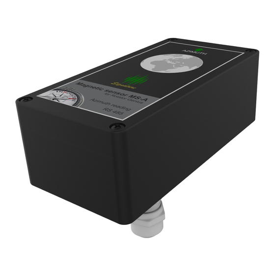
The arrow on the sticker shows the direction it is pointing.
This sensor must be as parallel to the ground as you can get it - not tilted at all.
Place the Sensor at least 80cm away from any metal materials and
ferromagnetics.
You can mount it to the aluminum antenna boom.
The sensor is placed in a plastic waterproof housing.
It is very light so you can use plastic cable strips for mounting.
In order to connect the sensor open the box by unwinding the four screws.
We recommend using an UTP network cable. The protocol used is RS485.
In order to connect the sensor to your PC you will need a USB to RS485 converter and a 12V power supply.
Two twisted wires are used for VDC, two twisted wires for GND and single wires in A and B for data.
Sensor wiring:
1.
ORANGE/WHITE
2.
ORANGE
3.
BLUE and BLUE/WHITE
4.
BROWN and BROWN/WHITE
Green is unused. We recommend to cut it off completely on
this end.
Once connected, the azimuth value will be displayed on the Rotator Genius LCD screen. Move it around and
verify it works before installing it on your antenna. It should be parallel to the floor and moved only in X and Y
axis so place it on a flat surface such as a table.
Azimuth Reader
Instruction Manual
A
to
B
to
VDC
to
GND
to
v1.0.0