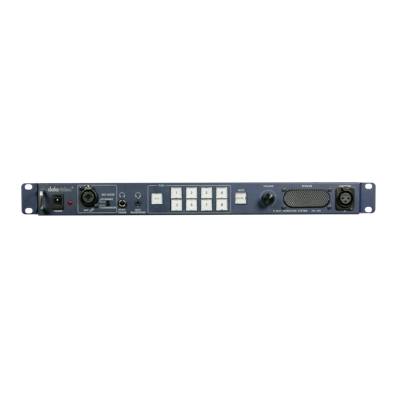
Datavideo ITC-100 KF1000 Руководство пользователя - Страница 13
Просмотреть онлайн или скачать pdf Руководство пользователя для Переключатель Datavideo ITC-100 KF1000. Datavideo ITC-100 KF1000 16 страниц. Patch panel
Также для Datavideo ITC-100 KF1000: Руководство по эксплуатации (14 страниц), Руководство по эксплуатации (6 страниц)

ITC100 Tally Input Pin Cross Reference
If you are using the ITC100 with a Datavideo RMC140, RMC90 or SE500 you do
not need to worry about tally information, as it is automatically sent to the ITC100.
If you are using the ITC100 with other equipment the following tables explain the
pin configurations of Tally A and Tally B.
Contact closure between the relevant Pin number and ground will illuminate the
LED. For example on Tally A, if Pin 1 is connected to Pin 4 the RED LED will light
up on Channel 1; if Pin 13 is connected to Pin 4 the AMBER LED will light up on
Channel 3
Tally A Input
The Tally A Input will send Tally Information to Channels 1 ~ 4. The following table
shows the pin numbers for each channel:
Video
Channel
1
2
3
4
Pins 4, 9 and 14 can be used as ground.
Tally B Input
The Tally B Input will send Tally Information to Channels 5 ~ 8. The following table
shows the pin numbers for each channel:
Video
Channel
5
6
7
8
Pins 4, 9 and 14 can be used as ground.
Red LED
LIVE
(On Air)
Pin 1
Pin 6
Pin 11
Pin 5
Red LED
LIVE
(On Air)
Pin 1
Pin 6
Pin 11
Pin 5
12
Amber LED
CUED
(Next)
Pin 3
Pin 8
Pin 13
Pin 15
Amber LED
CUED
(Next)
Pin 3
Pin 8
Pin 13
Pin 15
