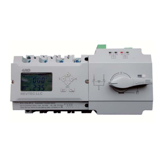
4PRO ATS-250A-4P-di Краткое руководство по эксплуатации - Страница 4
Просмотреть онлайн или скачать pdf Краткое руководство по эксплуатации для Переключатель 4PRO ATS-250A-4P-di. 4PRO ATS-250A-4P-di 7 страниц. Automatic transfer switch

Time and date setting
ON
N
R
OFF
Long press 5 second
Long press 5 second
Generator exerciser settings
The generator exerciser function needs the auxilary power supply (16VDC-24VDC) to be connected and current time and date settings
configured after it using time query and setting menu.
By default, the generator exerciser timer settings (parameters A-12 - A-22) are not configured.
To cancel the exerciser during the generator exerciser duration time, change the switch mode to manual and press any button.
Controller functions
Under/over-voltage detection: Controller monitors configured under/over voltage values of normal and reserve power supply
phases. When the under/over voltage is detected for one of the power supplies, the device controller automatically starts the load
transfer to another power supply. When the power supply vol t a g e i s recovered, the controller will transfer the load circuits back (auto-
recovery mode) or continues monitoring the power supplies (without auto-recovery).
Transfer delay:
When the normal (main) power supply voltage is abnormal and reserve (backup) power supply voltage is normal, the
controller switches to another power supply after the transfer delay counted. This delay value helps to avoid frequent load transfers in
case if the voltage recovers very quickly.
Recovery delay: This delay is activated before switching the load to normal (main) power supply when phase voltages are recovered
while the load circuits are powered via the reserve power source. It helps to insure that the normal power source voltage is stable before
switching the loads there.
Generator start delay: It helps to avoid frequent genset starts due to short time power issues. When main power faults, the delay
starts counting, and after the delay time is over, the generator start signal is activated.
(Note: this delay could be activated only if the auxilary 24VDC power supply is connected to the ATS switch)
Generator stop delay: This delay helps to remain the generator running in the hot backup state after the load is switched to the
normal power supply. The generator stop signal is activated after this delay to avoid genset restarts due to the main power supply
instability.
High/low frequency protection: it is adjustable within 20% range for the power supply phase frequency.
Generator exerciser timer: (daily, weekly and monthly timer setting).
Transfer modes:
Power grid Power grid (with autorecovery), Power grid Power grid (without autorecovery), Power grid Generator.
d-1:
year
under setting mode. Press
to increase, press
to decrease.
d-2:
month
under setting mode. Press
Normal Power over voltage transfer value set, Press
to increase, press
to decrease.
increase, press
decrease
d-3:
date
under setting mode. Press
to increase, press
to decrease.
d-4:
week
under setting mode Press
.
to increase, press
to decrease.
d-5:
hour
under setting mode Press
.
to increase, press
to decrease.
d-6:
minute
under setting mode Press
.
to increase, press
to decrease.
d-7:
secon
d under setting mode Press
.
to increase, press
to decrease.
–
1 or 3 Phase Power Source Settings
Press and release the SET button.
When you see "A-1", press and hold the SET button
again for 4 seconds until you see "E-1".
Use the arrow buttons to scroll down the menu until
you reach "E-2" value.
Set "E-2" value to 000 for 1 phase mode or to 001 for
3 phase mode.
Click on the "Auto/Man" button 2 times to exit the
menu.
50/60Hz Frequency Settings
Press and release the SET button.
When you see "A-1", press and hold the SET button
again for 4 seconds until you see "E-1".
Use the arrow buttons to scroll down the menu until
you reach "E-4" value.
Set "E-4" value to 000 for 60HZ or to 001 for 50HZ
settings.
Click on the "Auto/Man" button 2 times to exit the
menu.
Ph-N or Ph-Ph Voltage Display Settings
Press and release the SET button.
When you see "A-1", press and hold the SET button
again for 4 seconds until you see "E-1".
Use the arrow buttons to scroll down the menu until
you reach "E-3" value.
Set "E-3" value to 000 for Ph-N voltage display or to
001 for Ph-Ph voltage display.
Click on the "Auto/Man" button 2 times to exit the
menu.
NOTE: E-3" value must be set to 001 for
120/208VAC device version.
±
–
–
-
4
-
