4RF Aprisa SRi Краткое руководство по эксплуатации - Страница 11
Просмотреть онлайн или скачать pdf Краткое руководство по эксплуатации для Сетевой маршрутизатор 4RF Aprisa SRi. 4RF Aprisa SRi 12 страниц.

Page 11
Compliance Considerations
5.
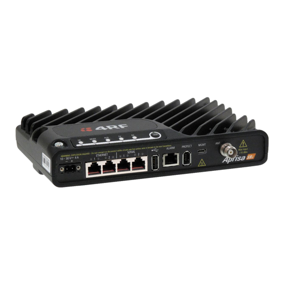
The Aprisa SRi is a professional radio product and as such must be installed by a suitably trained and qualified installer who is
aware of the local regulatory requirements existing at the time of installation and is capable of ensuring that the regulations
are adhered to.
The maximum Equivalent Isotropic Radiated Power (EIRP) permitted from the Aprisa SRi is regulated and must not exceed the
limits provided in the following table. To meet this regulatory requirement; knowledge of the antenna gain and feeder cable
loss must be known before setting the transmitter output power.
Regulatory Requirement
USA, FCC Part 15.247
Canada, ISED RSS-247
Australia, ACMA AS/NZS 4268
New Zealand, General User Radio
Licence for Short Range Devices
New Zealand, General User Radio
Licence for Short Range Devices
Brazil, Act No. 14.448, of December 4,
2017
Mexico, NOM-208-SCFI-2016
Peru
The Aprisa SRi has a maximum mean output power of +26 dBm into a 50 ohm antenna which equates to a maximum peak power
of +30 dBm PEP. To determine the maximum power to be set on the Aprisa SRi, the following installation parameters must be
known:
1.
Aprisa SRi equivalent average power for maximum permitted EIRP (specified in dBm)
2.
Antenna isotropic gain (specified in dBi)
3.
Feeder coax loss between Aprisa SRi and antenna (specified in dB/m)
4.
Length of feeder coax between Aprisa SRi and antenna (specified in metres)
From these the above information, the power setting of the Aprisa SRi (P
regulatory requirements using the formula:
Antenna gain information can be obtained from the Antenna manufacturer and is either expressed in terms of dBi, referenced
to an isotropic radiator, or dBd, referenced to a dipole.
If the gain is expressed in dBd, it can be converted to dBi by adding 2.15 dB to the gain value.
The following is an example of transmitter power calculations:
Antenna Type
Feeder Coax Length and Loss
and Gain
Yagi, 11 dBi
10 m of ½" Heliax @ 0.11 dB/m gives 1.1 dB loss
Panel, 12 dBi
33 m of RG214 @ 0.22 dB/m gives 7.3 dB loss
Dipole, 3.5 dBi
3 m of RG214 @ 0.22 dB/m gives 0.66 dB loss
Grid, 18 dBi
15 m of ½" Heliax @ 0.11 dB/m gives 1.65 dB loss
These are correct at the time of printing. The installer must ensure that the installation complies with the regulatory
1
requirements at the time of installation.
Frequency Range
902 MHz to 928 MHz
902 MHz to 928 MHz
915 MHz to 928 MHz
915 MHz to 928 MHz
920 MHz to 928 MHz
902 MHz to 907.5 MHz &
915 MHz to 928 MHz
902 MHz to 928 MHz
915 MHz to 928 MHz
=
+ (
×
/
Maximum
SRi Equivalent Maximum
EIRP
1
Average Power (R
+36 dBm PEP
+36 dBm PEP
+30 dBm
+30 dBm
+36 dBm
+36 dBm PEP
+36 dBm PEP
+30 dBm
) can be calculated to ensure operation within the
dBm
) −
Regulatory
Limit
+36 dBm PEP
+30 dBm
+30 dBm
+30 dBm
)
dBm
+32 dBm
+32 dBm
+30 dBm
+30 dBm
+36 dBm
+30 dBm
+30 dBm
+30 dBm
R
dBm
G
dBi
L
dB/m
d
m
Maximum SRi
Power Setting
22 dBm
25 dBm
26 dBm
13 dBm
