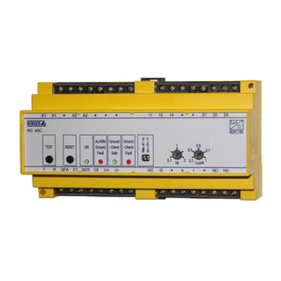
Bender RC48C Руководство - Страница 5
Просмотреть онлайн или скачать pdf Руководство для Монитор Bender RC48C. Bender RC48C 8 страниц. Ground-fault ground-continuity monitor

RI2000GC Melde- und Prüfkombination (Option) mit TEST-Taste
(T), RESET-Taste (R), „ALARM Ground Fault"-LED (GFA)
und „Ground Check Safe"-LED (GCS). Die Funktionen
der Tasten und LEDs entsprechen denen der gleich-
namigen Bedienelementen am RC48C.
M
Elektrischer Verbraucher, der über das überwachte
Kabel gespeist wird.
PW
Pilotdraht (Pilot wire)
EGC
Equipment grounding conductor = GND
F
Kurzschlussschutz Speisespannung.
Empfehlung: 6 A Sicherung.
Anschlüsse
A1, A2
Anschluss der Speisespannung U
11, 12, 14 und 21, 22, 24
Zwei freie Wechsler schalten im Alarmfall. Konfigura-
tion wahlweise als N/O oder N/C.
NC, NC
Kontaktkonfiguration für freie Wechsler einstellen:
Brücke offen:
Brücke geschlossen:
k, l
Anschluss Messstromwandler
GC
Anschluss an den Leiter PW (Pilot wire) des Kabels
G
Anschluss an den Leiter EGC (Equipment grounding
conductor = GND) des Kabels.
Anschluss der Melde- und Prüfkombination RI2000GC
T
Anschluss externe Test-Taste
R
Anschluss externe Reset-Taste
GFA
Anschluss externe LED „Alarm Ground Fault"
GCS
Anschluss externe LED „Ground Check Safe"
U+, U-
Ausgang DC 12 V, z. B. für Versorgung der Melde- und
Prüfkombination RI2000GC.
C1, C2, U+ Brücke versorgt Melde- und Prüfkombination
RI2000GC mit Speisespannung aus dem RC48C.
Technische Daten
Isolationskoordination nach DIN VDE 0110 T1:
Bemessungsspannung ........................................................................................................AC 250 V
Bemessungsstoßspannung/Verschmutzungsgrad .............................................................2,5 kV/3
Spannungsbereiche
Speisespannung U
........................................................................ AC/DC 60...264 V, 50...60 Hz
S
Für UL:
Speisespannung U
.......................................................................... AC/DC 110...240 V, 50/60 Hz
S
Sicherung .........................................................................................................empfohlen: 6 A träge
Eigenverbrauch..................................................................................................ca. 5 VA bei AC 60 V
...................................................................................................................... ca. 8,5 VA bei AC 264 V
Überwachung des Differenzstroms
Ansprechwert Differenzstrom ................................................einstellbar 0,1...1 A bzw. 1...10 A
Ansprechabweichung von I
/ A, (gültig für die Einstellbereiche x1 und x10)
Δn
bei Position „0,1" und „1"............................................................................................. 0...–25 %
bei Position „0,3" , „ 0,5" und „0,7".......................................................................................±20 %
Ansprechverzögerung ..................................................................................... einstellbar 0,1...2 s
Toleranz der Ansprechverzögerung ...................................................................................... ±20 %
Dauerkurzschlussstrom ........................................................................................................... 200 A
....................................................................................................................... 2500 A für 2 Sekunden
Arbeitsweise ............................................................................................... Fehlerspeicherverhalten
Überwachung des Schutzleiters
Ansprechwert Längsfehler ......................................................................................................... 40 Ω
Ansprechabweichung............................................................................................................. ±10 Ω
Leerlaufspannung..................................................................................................................DC 12 V
Impedanz des Ausgangs .......................................................................................................... 240 Ω
Nennstrom der Messschleife..............................................................................................DC 25 mA
RC48C_D00318_02_M_DEEN/07.2020
.
s
N/O
N/C (Werkseinstellung)
RI2000GC Remote alarm indicator and test combination (option)
with TEST button (T), RESET button (R), "ALARM
Ground Fault" LED (GFA) and "Ground Check Safe"
LED (GCS). The functions of the buttons and LEDs and
the designations correspond to the respective oper-
ating elements on the RC48C.
M
Electrical load supplied by the cable being monitored.
PW
Pilot wire
EGC
Equipment grounding conductor = GND
F
Short-circuit protection supply voltage.
A 6 A fuse is recommended.
Connections
A1, A2
Connection supply voltage U
11, 12, 14 and 21, 22, 24
Two voltage-free changeover contacts trip in case of
an alarm. N/C operation or N/O operation selectable.
NC, NC
Set contact configuration for voltage-free changeo-
ver contacts:
Bridge open:
Bridge closed:
k, l
Connection residual current transformer
GC
Connection to the PW (pilot wire) conductor of the cable
G
Connection to the EGC (equipment grounding con-
ductor = GND) conductor of the cable.
Connection to the RI2000GC remote alarm indicator and test
combination
T
Connection external Test button
R
Connection external Reset button
GFA
Connection external "Alarm Ground Fault" LED
GCS
Connection external "Ground Check Safe" LED
U+, U-
Output DC 12 V, e.g. for the supply of the RI2000GC re-
mote alarm indicator and test combination.
C1, C2, U+ Bridge supplying the RI2000GC remote alarm indica-
tor and test combination with supply voltage from
the RC48C.
Technical data
Insulation coordination acc. to IEC 60664-1:
Rated insulation voltage...................................................................................................... AC 250 V
Rated impulse voltage/pollution degree............................................................................. 2.5 kV/3
Voltage ranges
Supply voltage U
.......................................................................... AC/DC 60...264 V, 50...60 Hz
S
For UL:
Supply voltage U
.............................................................................AC/DC 110...240 V, 50/60 Hz
S
Fuse..................................................................................................... recommended: 6 A slow fuse
Power consumption ....................................................................................approx. 5 VA at AC 60 V
................................................................................................................approx. 8.5 VA at AC 264 V
Residual current monitoring
Response value, residual current ................................................adjustable 0.1...1 A or 1...10 A
Accuracy of I
/ A, (valid for setting ranges x1 and x10)
Δn
at position "0.1" and "1"................................................................................................ 0...–25 %
at position "0.3", "0.5" and "0.7"......................................................................................... ±20 %
Response delay ................................................................................................. selectable 0.1...2 s
Accuracy of the response delay............................................................................................. ±20 %
Continuous short-circuit current.............................................................................................. 200 A
..........................................................................................................................2500 A for 2 seconds
Operating mode ....................................................................................................................latching
Ground conductor monitoring
Response value, series resistance fault .......................................................................................40 Ω
Accuracy.................................................................................................................................. ±10 Ω
Open-circuit voltage.............................................................................................................. DC 12 V
Output impedance.................................................................................................................... 240 Ω
Rated current of the measuring loop.................................................................................DC 25 mA
.
s
N/O
N/C (factory setting)
5
