Bender RC48N Руководство - Страница 4
Просмотреть онлайн или скачать pdf Руководство для Монитор Bender RC48N. Bender RC48N 12 страниц. Ground-fault neutral-grounding monitor
Также для Bender RC48N: Руководство (8 страниц)
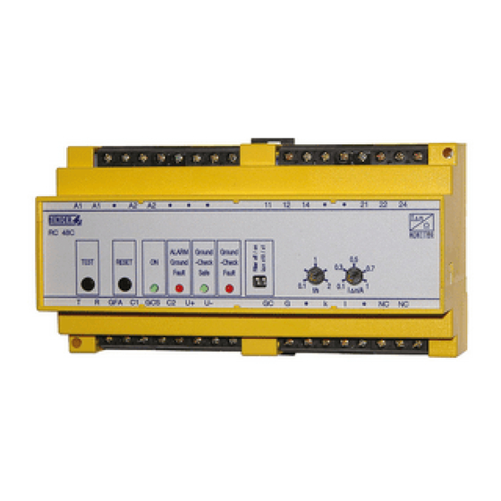
Bedien- und Anzeigeelemente
Legende
Beschreibung
TEST-Taste drücken löst folgenden Ablauf aus: Ein Test-
Differenzstrom wird simuliert, nach Ablauf der Ansprechzeit
wird ein Alarm erkannt, das Alarmrelais schaltet und
die LED „ALARM Ground Fault" leuchtet. Die Alarmmeldung
wird gespeichert.
RESET-Taste drücken: löscht Alarmmeldungen
ON-LED (grün) leuchtet, wenn RC48N im Betrieb ist.
LED „ALARM Ground Fault" (rot) leuchtet, wenn der An-
sprechwert des Differenzstroms und die Ansprechzeit
überschritten sind.
LED „ALARM Resistor Fault" (rot) leuchtet, wenn Ansprech-
wert für Spannungsabfall am Erdungswiderstand
überschritten ist oder wenn der Erdungswiderstand größer
als 2 kΩ ist.
DIP-Schalter:
Filter off/on: Bandpassfilter 50...60 Hz
Ist der Bandpassfilter eingeschaltet, werden ausschließlich
die 50...60 Hz-Komponenten des Differenzstromes
schmalbandig erfasst. Diese Funktion kann verwendet
werden, um Fehlauslösungen durch harmonische und
transiente Komponenten im Differenzstrom zu vermeiden.
I
x 10/x 1: Einstellbereich für den Ansprechwert des
Δn
Differenzstroms I
/A einstellen:
Δn
x 1 0,1 A...1 A
x 10 1 A...10 A.
4
RC48N_D00426_00_M_DEEN / 08.2020
Operating and display elements
Legend
1
Pressing the TEST button initiates the following sequence:
a test residual current is simulated, after the expiry
of the response time an alarm is recognized which
causes the alarm relay to switch and the "Alarm Ground
Fault" LED to light up. The alarm message is stored.
2
Pressing the RESET button deletes alarm messages.
3
ON LED (green) lights up indicating that the RC48N is in
operation.
4
"Alarm Ground Fault" LED (red) lights up when the ground
fault current exceeds the alarm response value and the
time delay.
5
"Alarm Resistor Fault" LED (red) lights up when the
voltage across the neutral grounding resistor exceeds the
preset value or when the NGR's resistance exceeds 2 kΩ.
6
DIP switch:
Filter off/on: bandpass filter 50...60 Hz
When the bandpass filter is switched on, only the narrow-
band 50...60 Hz components of the residual current are
detected. This function can be used to avoid false trippings
caused by the occurrence of harmonics and transient
components in the residual current.
I
x 10/x 1: for setting the residual current response
Δn
value I
/A:
Δn
x 1 0,1 A...1 A
x 10 1 A...10 A.
Description