Bresser F004518 Руководство по эксплуатации - Страница 3
Просмотреть онлайн или скачать pdf Руководство по эксплуатации для Аксессуары Bresser F004518. Bresser F004518 13 страниц. Electric background system
GENERAL ASSEMBLY INSTRUCTIONS
• Before assembly, remove all accessories from the package and lay them out on a level surface.
• Only use screws and, if necessary, dowels that provide a sufficiently high load-bearing capacity (minimum 25 kg per roll incl. all attachments).
• Only connect the individual electronic components with the connection/power cables supplied.
ATTENTION: Do not install defective cables and/or electronic parts and do not put them into operation!
MOUNTING
(Fig. 2-5)
Fig. 2
G
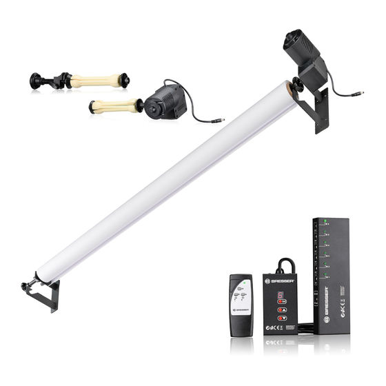
Step1:
1. Push one roll holder
(G) with and one without motor (H) left
2
and right into the paper tubes or aluminium tubes
background rolls.
2. Fix the roll holders in the tube/aluminium pipe with the knurled
screws (22).
IMPORTANT: For background rolls wound on cardboard tubes, the
cardboard tube should be replacedby an aluminium tube
sagging or kinking!
Fig. 4
Step 3:
Hook the background rolls, which are preassembled with roll holders
and motor, into the hooks (20) on the left and right at the desired
levels.
IMPORTANT: It is strongly recommended to lift the background rolls
only with two persons and to hook them into the hooks due to the high
weight!
Fig. 5
A
M-6
M-5
M-4
M-3
M-2
M-1
DC
depending on model with 2, 3, 4 or 6 hooks /
1
G
of the
3,4
M-6
M-5
to prevent
3,4
M-4
M-3
M-2
M-1
DC
Step 4:
1. Mount the motor panel
(A) near the motors using
suitable screws and, if
necessary, dowels.
2. Insert the hollow plugs of
the motor cable (23) into the
desired motor connection
sockets (1) of the motor panel
(A).
depending on model 2, 3, 4 or 6 pieces included /
2
Fig. 3
D
H
Front
Page
Step2:
1. Measure the length of the background roll incl. mounted roll
holder and motor connection.
2. Mount the hook units1 (D) to the left and right of the wall or
ceiling using suitable screws and, if necessary, dowels.
IMPORTANT: Precise vertical and horizontal alignment must be
ensured!
POWER SUPPLY 6)
Fig. 6
MOTORS & PANEL
1. Insert the hollow plug of the power supply cable (16) into the
power connection socket (3) of the motor panel (A).
2. Insert the C12 plug (18) into the C12 connection socket (15) on.
3. Insert the Euro plug into the mains power socket.
The function light (16) lights up. The power supply is established.
REMOTE CONTROL
1. Open the battery compartment (14).
2. Insert the batteries according to the indicated pole orientation (+/-).
3. Close the battery compartment (14) again.
not included /
available in hardware stores; use recommended for safety reasons
3
4
D
M-6
M-5
M-4
M-3
M-2
M-1
DC
M-6
M-5
M-4
M-3
M-2
M-1
DC
Page
Front