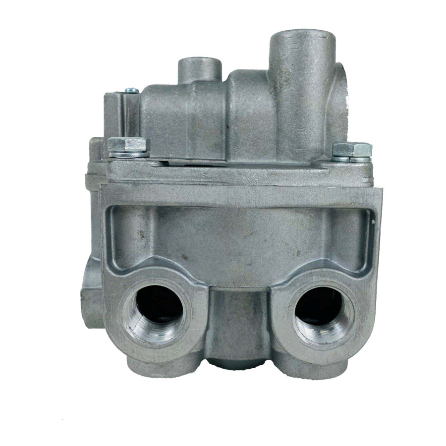
BENDIX BP-R1 BOBTAIL PROP RELAY VALVE Руководство - Страница 7
Просмотреть онлайн или скачать pdf Руководство для Блок управления BENDIX BP-R1 BOBTAIL PROP RELAY VALVE. BENDIX BP-R1 BOBTAIL PROP RELAY VALVE 11 страниц. Bobtail proportioning relay valve

™
6. Check the BP-R1
valve differential pressure by apply-
ing 10 psi to the service port and noting the pressure
registered at the delivery port. Subtract delivery port
pressure from the 10 psi service pressure to obtain the
differential. Compare the measured differential with the
pressure specifi ed for the BP-R1
Note: For BP-R1
™
valves not incorporating a relay
piston return spring (14), the measured differential
should be approximately 4 psi. When a spring is in use,
the differential will be higher (see the I.D. washer also
for the differential).
7. Make and hold a full (100 psi or greater) brake
application and note that full pressure is delivered to
the chambers.
8. Activate the dash mounted trailer supply valve for
bobtail tractor operation. Then make a slow brake
application, increasing the pressure at the BP-R1
valve service port to 20 psi while watching the reaction
at the delivery port gauge. Note that delivery pressure
rises to approximately 5 to 10 psi and remains constant
while service pressure continues to rise to 20 psi.
Release the application.
9. Make another brake application and slowly increase the
pressure at the BP-R1
60 and 70 psi while observing the gauge installed at
the delivery port. Note that when service port pressure
rises to between 20 and 30 psi, delivery pressure begins
to rise above the initial pressure noted in step 6. The
rise of delivery pressure should be at a proportioned
rate of approximately 3:1. At 70 psi service pressure,
delivered pressure should be 15 to 25 psi.
10. Make a full brake application and note that both test
gauges register the same pressure.
11. Drain air pressure from all vehicle reservoirs and
remove the test gauges from the BP-R1
LEAKAGE TESTS
1. Build the air system pressure to governor cut-out. With
the dash mounted trailer supply valve activated for
tractor/trailer operation, apply a soap solution to both
exhaust ports (one in the cover and one in the body).
The leakage noted should not exceed a 1" bubble in
less than 3 seconds at any exhaust port.
2. Make and hold a full brake application and apply a
soap solution to both exhaust ports and around the
cover where it joins the body. The leakage noted should
not exceed a 1" bubble in less than 3 seconds at any
exhaust port.
VALVE REMOVAL
1. Park the vehicle on a level surface and block the wheels
and/or hold the vehicle by means other than the air
brakes.
™
valve part number.
™
valve service port to between
™
valve.
2. Drain the air pressure from all vehicle reservoirs.
3. Identify and mark or label all air lines and their
respective connections on the valve to facilitate ease
of installation.
4. Disconnect all air lines.
5. Remove the valve from the vehicle.
VALVE INSTALLATION
1. Install all air line fi ttings and plugs making certain thread
sealing material does not enter the valve.
2. Install the assembled valve on the vehicle.
3. Reconnect all air lines to the valve using the identifi ca-
tion made during VALVE REMOVAL (step 3).
4. After installing the valve, test all air fi ttings for excessive
leakage and tighten as needed.
™
DISASSEMBLY
GENERAL
The following disassembly and assembly procedure is
presented for reference purposes only and presupposes
that the appropriate maintenance kit is on hand at the time
of disassembly. The instructions provided with the mainte-
nance kit should always be used in lieu of those presented
here. Refer to Figure 10 throughout the disassembly and
assembly procedure.
Caution: The BP-R1
bench vise during disassembly, however, overclamp-
ing will cause damage to the valve and result in leakage
and/or malfunction. If a vise is to be used, position the
valve so that the jaws bear on the supply ports on opposing
sides of the valve's body.
1. Remove all air fi ttings and plugs from the valve.
2. Mark the relationship of the valve cover to the body and
if the valve is equipped with a mounting bracket, mark
the relationship of the bracket to the cover.
3. While holding the exhaust cover (4), remove and
discard the retaining ring (3) that secures it to the body
(1).
4. Remove and discard the exhaust cover (4) along with
both o-rings (5 & 6).
5. Remove and discard the valve spring (7), valve retainer
(8), and the valve assembly (9) from the body (1).
6. Remove and retain the four cap screws (10) that secure
the cover (2) to the body (1).
7. Separate the cover (2) from the body (1), then remove
and discard the sealing ring (35) and o-ring (11).
8. Remove and retain the relay piston (13) and relay piston
spring (14) from the body (1).
Note: The relay piston spring, item 14 is not used in
all valves.
™
valve may be lightly clamped in a
7
