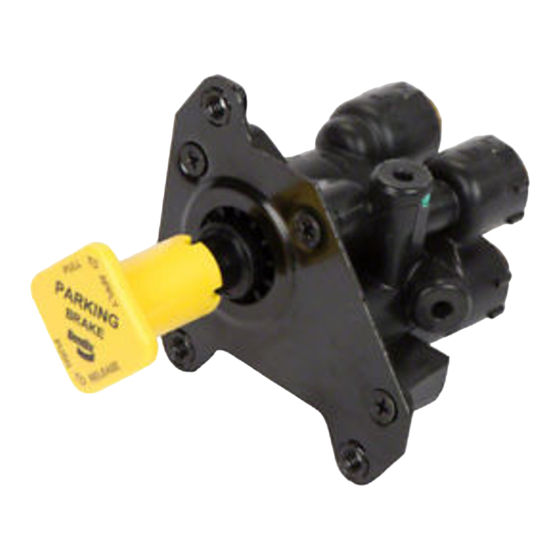
BENDIX PP-DC Руководство - Страница 6
Просмотреть онлайн или скачать pdf Руководство для Блок управления BENDIX PP-DC. BENDIX PP-DC 7 страниц. Park control valve

3. With the button in, coat the exhaust port and the plunger
stem with a soap solution. Leakage at both areas should
not exceed a 1" bubble in 3 seconds.
OPERATIONAL TEST
1. With the button out, supply either supply port with 120
psi of air. Then push the button in. Air pressure should
rise in the delivery volume equivalent to supply pressure.
2. Pull the button out. Delivery pressure should exhaust to
0 psi.
3. Build each supply source to 120 psi. Decrease supply
pressure at the secondary service reservoir supply port
at a rate of 10 psi per second. Primary supply pressure
and delivery pressure should not drop below 100 psi.
Repeat the test for decreasing primary service reservoir
pressure.
4. Build each supply source to 120 psi. Then decrease
both supply pressures to below 20 to 30 psi. The button
should automatically "pop" out when pressure drops
within that range.
If the PP-DC
™
valve fails to function as described, or if
leakage is excessive, repair the valve or replace it at the
nearest authorized Bendix Commercial Vehicle Systems
parts outlet.
REMOVAL
1. Identify and mark or label all air lines and their
connections on the valve.
™
2. Remove the PP-DC
valve from the vehicle and save the
mounting hardware.
INSTALLATION
1. Install the PP-DC
™
valve in its location on the dashboard.
Using the mounting hardware saved in "REMOVAL,"
secure the valve to the vehicle.
2. Reconnect all air lines to the valve using the identification
made in "REMOVAL."
3. Perform "OPERATIONAL AND LEAKAGE TESTS" before
placing the vehicle back in service.
DISASSEMBLY
The following disassembly and assembly procedures are
for reference only. Always have the appropriate maintenance
kit on hand and use its instructions in lieu of those presented
here. Refer to Figure 6 throughout the procedure.
1. Turn the button counterclockwise to remove it from the
plunger stem.
2. Remove the four screws that secure the cover to the
body, and remove the cover.
3. Pull the plunger stem to remove the plunger and the
guide spool from the body.
4. Remove plunger spring(6) and discard.
6
BW1739 © 2007 Bendix Commercial Vehicle Systems LLC. All rights reserved. 6/2007 Printed in U.S.A.
5. If necessary, use a screwdriver to carefully remove the
check valve seat from the body. Be sure not to damage
the check valve seat or the body.
6. Remove and discard check valve seat o-rings(7) and (8).
7. Turn the body upside down and gently tap it on a flat
surface to remove check valve(9). Discard the check
valve.
8. Remove the guide spool from the plunger. Remove and
discard o-ring(1) from the guide spool.
9. Remove and discard o-rings(2), (3) and (5) from the
plunger. Also remove and discard exhaust seal(4).
CLEANING & INSPECTION
1. Wash all metal parts in mineral spirits and thoroughly
dry.
2. Inspect all re-usable parts for excessive wear or damage.
Inspect the body for gouges or deep scuffing. Replace
key numbers 1-9 (and any parts not determined usable)
with genuine Bendix replacements.
ASSEMBLY
Before assembly, lubricate all o-rings, o-ring grooves, rubbing
surfaces and bores with Bendix silicone lubricant (Pc. No.
291126) or equivalent.
1. Place check valve(9) into its seat in the body with its flat
surface facing upward. If necessary, reach into the body
to make sure the valve is seated evenly in the bore.
2. Install o-rings(7) and (8) on the check valve seat and
install the check valve seat into the body. Make sure the
seat is fully seated-its surface should be even with the
body's surface.
3. Install plunger spring(6) into the body. Make sure it stands
upright and is seated properly in the body bore. (It should
surround the protrusion or "lip" at the bottom of the body
bore.)
4. Install o-rings(2), (3), (5) and exhaust seal(4) onto the
plunger. Then install the plunger into the body. Line up
the plunger's index tabs with the spaces in the body
bore for ease of installation.
5. Install o-ring(1) onto the guide spool. Then install the
guide spool over the plunger and into the body. Press
the guide spool into place firmly.
6. Place the cover onto the body and secure with its four
screws. Torque to 35 in. lbs.
7. Thread the button clockwise onto the plunger stem. It
should take approximately 3 full button revolutions to
install it on the plunger. The protrusions on the side of
the plunger should line up with the button grooves. Push
on the button a number of times to make sure the plunger
moves freely throughout its range of motion.
NOTE: BEFORE PLACING THE VEHICLE BACK INTO
SERVICE, PERFORM THE "LEAKAGE AND
OPERATIONAL TESTS" IN THIS MANUAL.
